- Catalogs
- Fracsun Inc
- ARES Installation Manual
ARES Installation Manual
1 /15Pages

ARES Installation Manual
1 /15Pages
Catalog excerpts

ARES Soiling Measurement System Installation Manual Model CS4 Revision F Release date: August 17, 2021
Open the catalog to page 1
Important Safety Instructions WARNING: TO PREVENT FIRE, ELECTRIC SHOCK AND DAMAGE, DO NOT EXPOSE THE INTERNAL COMPONENTS (CIRCUITS BOARDS AND WIRES) TO RAIN OR MOISTURE. Read these instructions. Keep these instructions. Follow all instructions. Do not submerge the device(s) in water or liquid. Do not install the ARES device directly on solar module frames. Do not leave the ARES device powered on without sun (like indoors) for more than 24 hours. The battery will fully discharge and may take more than 2 hours with full sun to recharge. Never leave the Wash Extension solar panel glass facing down...
Open the catalog to page 2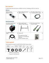
Box contents The ARES soiling measurement system is shipped in two boxes. The following contents are in each box: ARES box ARES CS4 Soiling Measurement Device External cellular whip antenna (SMA connection) Flex tubing, 3 meter, 1/8” ID, ¼” OD (pre-attached to ARES) Gen3 Wash Extension device (solar panel attached) Bottom support bracket (attached to Wash Extension) M12 communication cable, RS-485, 3 meters Corrugated sheathing, 3 meters 4x Threaded ground spike 4x 3/8”-16 x 1” hex head screw 3x Zip ties 1x Hose compression sleeve Tools required The following tools are required to install the...
Open the catalog to page 3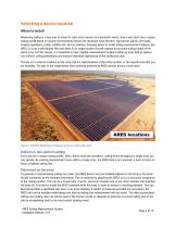
Selecting a device location Where to install Measuring soiling is a new area of study for solar asset owners and operations teams. Every solar plant has a unique soiling profile based on several environmental factors like dominant wind direction, agricultural activity, dirt roads, mowing operations, pollen, wildfire ash, and air pollution. Knowing where to install soiling measurement stations, like ARES, is a not a well-studied field and there is no single location that will capture an accurate soiling model of the entire array. For this reason, it is beneficial to have multiple measurement locations...
Open the catalog to page 4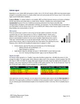
Cellular signal Depending on your model, ARES will operate on either a 3G or LTE CAT-M1 network. ARES must have decent signal strength to successfully connect to a nearby cellular tower and communicate with the Fracsun cloud. A site survey is highly recommended before installation. A note on Modbus: If a cellular network is not available, ARES and Wash Extension devices can function as Modbus RS-485 slave devices and stream data to a master device. However, a Modbus-only communication is not recommended because of the loss of additional processing performed in the Fracsun cloud (like daily soiling/insolation...
Open the catalog to page 5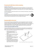
Preparing the ARES device before mounting Automatic wake in the sun ARES devices are shipped in a deep-sleep mode state, which preserves the battery for up to 45 days while in the box. When placed in the sunlight (specifically greater than 250 W/m2), ARES will wake from deep-sleep within 20 minutes (sometimes less) and start connecting to the nearest cellular tower. Once a connection is established, ARES will begin normal operation. This feature allows ARES to startup without opening the unit and connecting the internal battery. Just place ARES in the sun, and it will power up. Low battery If...
Open the catalog to page 6
HSAT bracket hardware list: • • • • • • • (1) HSAT Bracket (2) 1/4-20 x ½" flat head screw (2) 5/16-18 threaded rod with locking nuts (1) 9” length shallow strut channel (2) 5/16” fender washers (2) 5/16” locking washers (2) 5/16”-18 hex nut Figure 4: Mounting ARES to the torque tube (not shown). Fixed-tilt system using Purlin Bracket Kit For fixed tilt systems, the Purlin Bracket Kit (PBK) is attached to a purlin or rail. ARES then mounts directly to this rail if there is no correction needed to ensure the measurement plane is parallel to that of the array. The Purlin Bracket Kit contains the...
Open the catalog to page 7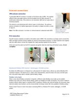
External connections SMA antenna connection A gold-plated SMA RF connector is located on the bottom-side of ARES. The supplied cellular di-pole whip blade antenna must be threaded onto the SMA connector to send/receive cellular data. If the antenna is not connected, ARES will not output data or functional properly. The antenna is omni-directional with uniform power in all directions. The optimum antenna orientation for highest signal power and quality is straight (not bent), as seen in Figure 6. Note: If the SMA connector is not there, an internal antenna is attached inside ARES. Figure 6: Blade...
Open the catalog to page 8
Wash Extension Installation Rinsing fluid Fluid type The wash extension can hold up to 16 gallons of rinsing fluid. The fluids list below are highly recommended for high soiling accuracy. Under no circumstances should tap water be used. Tap water contains minerals that will build up on the solar glass after each wash, affecting the irradiance measurement and soiling accuracy. • • Distilled water Filtered water (RO + DI preferred) with a TDS (total dissolved solids) value of less than 20 Number of days Each rinse uses roughly 5 ounces of water per spray, allowing for about 360 rinses. A future...
Open the catalog to page 9
Removing the solar panel To continue with installation, the solar panel must be removed to gain access to the Wash Extension enclosure cover, M12 connection, and pump output barb. Remove the 4 machine screws (2 per side) as seen in Figure 9 and set the solar panel aside. The machine screws are #12-24 x 3/8” L, pan head Phillips. Figure 9: Remove the solar panel by removing these machine screws. Connecting the flex tubing and communication cable To enable the daily automatic cleaning and feedback, the included flex tubing and M12 communication cable must be connected between the Wash Extension...
Open the catalog to page 10
Opening the electronics enclosure and powering up for the first time The battery inside the Wash Extension enclosure is shipped disconnected to avoid over-discharge. The enclosure must be opened to reconnect the battery and power-up the Wash Extension Control (WEC) PCB. 1. 2. 3. 4. Loosen the 4 Phillips-head screws from the top of the Wash Extension enclosure cover. Remove the cover and set aside. Connect the loose Faston connector into the battery terminal as seen in Figure 14. Verify that the LED (Figure 15) activity on the WEC PCB has the following order: a. Fading white: processing code (~...
Open the catalog to page 11All Fracsun Inc catalogs and technical brochures
 WASH EXTENSION V4
1 Page
 PV Soiling Monitoring Solution
21 Pages
 CLEO
CLEO2 Pages
 ARES Modbus Documentation
15 Pages