
- Catalogs
- FRABA VITECTOR
- PRODUCT OVERVIEW

PRODUCT OVERVIEW

PRODUCT OVERVIEW
The document provides a detailed overview of safety systems for industrial applications, focusing on safety edges, their components, installation, and applications. It highlights two main types of safety edges: Opto-electronic Safety Edge (OSE) and Pneumatic Switch (DW), detailing their functions, advantages, and installation procedures.
The OSE is a high-safety system approved by German and UL standards, featuring a modular design for easy assembly and high reliability. It uses an infrared safety light barrier within a rubber profile, which interrupts the light beam when deformed, triggering a safety response. Key advantages include simple assembly, high environmental stability, and flexibility. However, it cannot connect multiple safety edges in series and has limitations on bending angles.
The DW system is cost-effective and flexible, designed for user assembly. It operates by detecting pressure waves generated by the deformation of the signaling element, converting them into electrical signals for processing.
Safety edges are crucial in various applications where moving edges pose hazards, such as automatic gates, machine safety hoods, and train doors. They must meet safety, reliability, and cost-efficiency requirements.
The document references several standards, including DIN EN 1760-2 and DIN EN 954-1, which govern the safety categories and requirements for doors and gates.
The OSE system's modular design allows for easy installation without special tools. Components include transmitters, receivers, rubber profiles, and control units. The system is designed for high resistance to environmental factors and vandalism.
The document emphasizes the importance of safety edges in industrial applications, detailing their design, functionality, and compliance with safety standards. It highlights the benefits of modular design and the need for reliable, cost-effective safety solutions.
The OSE system ensures safety by interrupting an optical channel when the safety edge is actuated. The system is self-controlled, with actuation forces independent of profile length, determined by gate speed and profile shape. Various profile shapes are available, and custom profiles can be produced cost-effectively.
The control unit analyzes signals per EN ISO 13849-1, available in categories 1 to 4, meeting all safety requirements. It can be integrated into gate control systems, with various housing options and plug-in cards for different applications.
Installation involves attaching the signaling element, connecting the signal transmission device, and connecting the control unit. Testing is required post-installation to ensure proper function. Regular maintenance by specialists is recommended.
Components can be replaced on-site by skilled personnel. The process involves cutting the rubber profile and mounting rail, inserting sensors, and connecting them to the control unit.
The DW switch converts pressure waves into electrical signals. It features adjustable sensitivity and can be mounted in various housings. The system is not self-monitoring, requiring external testing for certain safety standards.
The DW switch is cost-effective, easy to assemble, and flexible in application. It allows for quick repairs and minimizes downtime.
Involves cutting the rubber profile, connecting stoppers, and linking the pressure-wave switch to the control system. Sensitivity adjustments are made via an adjustment screw.
Safety edges are used in doors, gates, vehicle construction, and mechanical engineering to prevent hazards. They are essential in applications where moving edges pose safety risks.
For automatic operation, a safety edge is installed on the main closing edge. The profile must have sufficient over travel and be compatible with the gate panel. The control unit and sensors are selected based on the gate control system.
The document outlines the specifications for safety edges used in various applications, such as folding gates, machine doors, and train doors. Key components include profiles, sensors, control units, and accessories like end stoppers and junction boxes. Profiles must accommodate specific chamber sizes, typically 11 mm, and be capable of actuating from angles.
Safety edges must be integrated into gate control systems to interrupt self-holding functions and ensure gates operate in dead-man mode if the safety edge fails. Limit switches require adjustment to prevent crushing of sensing chambers. The document emphasizes the importance of reversing gates upon receiving a signal to rise or reopen.
Examples include safeguarding folding gates, industrial washing machine doors, and train doors. Each application requires a risk analysis to determine the appropriate profile and control unit. Performance Level requirements are specified according to EN ISO 13849-1, with considerations for over travel and sensor wiring.
Safety edges must comply with European Directives on machine safety, electromagnetic compatibility, and low-voltage installations. Conformity is certified by authorized institutes like TÜV. Harmonized standards, such as DIN EN 1760-2, provide guidelines for design and testing of safety edges.
The selection process involves assessing the required safety category, performance level, and stopping path. Force-travel diagrams help in choosing the appropriate safety edge based on operating speed and over travel requirements. The document stresses the importance of ensuring that forces acting on individuals do not exceed permissible limits.
DIN EN 1760-2 and DIN EN 954-1/EN ISO 13849-1 are key standards governing safety edges. They define design principles, safety categories, and testing requirements. Safety edges must be tested as complete systems, including signaling elements and control units, to ensure compliance with safety directives.
The document outlines safety categories for machinery, specifically focusing on safety edges for doors and gates. It categorizes safety into four levels (Category 1 to 4) based on the severity of potential injuries, frequency of exposure, and the possibility of avoiding hazards. Each category has specific requirements, such as the use of established safety principles and the ability to detect faults.
European standards like DIN EN 12453, DIN EN 12445, and DIN EN 12978 are highlighted, which govern the safety of power-operated doors and gates. These standards ensure that doors and gates are constructed and operated safely to prevent endangering people.
EN ISO 13849-1 introduces five Performance Levels (PL) that require a risk evaluation to determine the appropriate level for specific applications. Examples are provided for safeguarding edges in gates and driver-less transportation systems, indicating the necessary Performance Levels.
The document lists certified safety edge systems by FRABA VITECTOR, detailing their components and safety categories. These systems are certified by the Technical Inspection Authority (TÜV) and meet various safety categories and performance levels.
Technical data for OSE sensors and OPTOCHAIN systems are provided, including protection class, operating temperature, material specifications, and connection diagrams. The OPTOCHAIN system allows for serial connection of multiple safety edges, optimizing safety edge usage for devices.
The OPTOCHAIN system is suitable for various applications, such as revolving doors and sliding gates. It complies with DIN EN ISO 13849-1:2008 category 3 PL d, ensuring it meets safety requirements for machine protection. The document emphasizes that no modifications or repairs should be made to the OPTOCHAIN components during operation.
The document provides technical specifications and descriptions for various VITECTOR products, including OPTOCHAIN, OPTOCORD, and OPTOGUARD systems. These systems are designed for safety edge applications in automated doors, ensuring obstacle detection and safe operation.
- Components: Includes Master Transmitter (OPC-MT), Slave Transmitter (OPC-ST), and Receiver (OPC-R).
- Specifications: IP68 protection, operating temperature from -20°C to +75°C, range up to 10m, power supply 3V to 24V DC, and max current consumption of 20mA.
- Safety: Complies with EN 13849-1:2008, safety category 3, performance level d, with a maximum operation period of 20 years.
- Description: Designed for two parallel safety edges, suitable for wider door profiles, using a single interface for multiple sensors.
- Specifications: IP67 protection, similar operating conditions as OPTOCHAIN, with a focus on simplified wiring and installation.
- Components: Includes fixed part (OPT-CF) and moving part (OPT-CM), with low-power OSE sensors.
- Functionality: Wireless signal transmission, replacing traditional spiral cables, with a focus on reducing installation complexity and enhancing reliability.
- Specifications: Safety category 3, IP54 protection, operating temperature from -20°C to +55°C, and battery life exceeding 2 years.
- Description: Pre-traveling light barrier system with telescopic sledges for obstacle detection in doorways.
- Specifications: Range from 1.5m to 7m, IP65 protection, operating temperature from -10°C to +55°C, and power consumption of 60mA.
- Variety: Multiple control units available for different safety edge configurations, with varying safety categories and power supply requirements.
- Installation: Requires qualified electricians for installation, with specific guidelines for safe operation and maintenance.
- Inspection: Annual visual inspections are recommended for sensing edges to check for damages or decreased flexibility.
- Warning: Proper handling, transportation, and storage are crucial for the safe operation of these devices.
This document provides technical specifications, safety characteristics, and operational guidelines for various models of the OSE control units and opto-edge sensors, specifically the OSE-C 4524, OSE-C 1001, OSE-C 2300/2301, and OSE-C 2323/2324. These devices are used for automated doors and gates, ensuring safety and compliance with European standards.
- Safety Characteristics: The OSE units comply with safety categories Cat. 1, 2, and 3 according to EN ISO 13849-1, with performance levels ranging from PL c to PL d. They are certified by TÜV and UL.
- Technical Data: The units operate at a supply voltage of 24 V DC or 230 V AC, with varying power consumption and protection classes ranging from IP 40 to IP 65. They are designed to function in temperatures from -20°C to +55°C.
- Relay Data: The relays have a maximum operating voltage of 250 V AC/DC and can handle currents up to 6 A, with a mechanical service life of up to 30 million switching cycles.
- Mounting Instructions: The control units should be mounted with sufficient distance from heat sources and on non-vibrating surfaces. Specific mounting instructions are provided for each model.
- Connection and Wiring: Detailed terminal assignments and wiring diagrams are provided for connecting the OSE units to power supplies and safety edges. Proper terminal connections are crucial for the correct operation of the safety features.
- Operation and Testing: The units do not require an external reset signal and comply with DIN EN 1760-2 standards. Testing inputs and output contacts are used to monitor and signal the condition of safety edges.
- LED indicators provide status updates and error notifications. Common issues include power supply errors, incorrect terminal assignments, and defective safety edges. Remedies involve checking connections, ensuring unobstructed light paths, and verifying power supply.
- Ensure all safety-related parts are properly mounted and functioning by manually triggering sensing edges.
- Regularly inspect and maintain the units to prevent faults and ensure compliance with safety standards.
The document outlines various components and specifications related to OSE (Opto-electronic Safety Edge) systems, including transmitters, receivers, and cable sets. Key components include 4-pole and 5-pole terminals, safety switch interfaces, and power supply requirements (+12 V DC). The document also details LED assignments for indicating defects and operational statuses.
Offset brackets AC 2001 and AC 2002 are made from galvanized steel and are used to prevent cable damage by securing the coil cord to the guide rail or wall. They come with M16 bend protection and are designed for sectional doors and rolling shutters.
OSE cable sets include junction boxes, spiral cables, and cable gland accessories. They are available in standard and advanced versions, with the latter featuring a diagnostic PCB. Different sets are designed for various door types, such as roller shutters and sectional doors.
The document lists various bumper models made from polypropylene, with specifications on dimensions and screw types. Bumpers are available in one-piece and modular designs.
End covers are used for closing opto-electronic safety edges, primarily in sliding gates or machine construction. They are made from thermoplastic elastomers and are oil-resistant.
The DiagnOSE OSE-A 1010 tool is used to analyze malfunctions in automatic doors. It connects between the door control unit and the safety edge, allowing users to test and diagnose issues with transmitters, receivers, or rubber profiles.
Various pneumatic switches (DW series) are described, including normally open, normally closed, and changeover contacts. Technical data includes diaphragm material, contact loads, and response sensitivity. The document also details mounting possibilities and connector types.
The document describes signal sources like push buttons and rubber profiles used in safety systems. Rubber profiles are made from materials like NBR and EPDM, with specifications on resistance to various environmental factors.
The Raytector is a single-beam light barrier used as a safety measure in power-operated gate installations. It consists of a light transmitter and receiver, ensuring safety by detecting interruptions in the light beam.
The document provides technical specifications and installation guidelines for the RAYTECTOR and FLASHENTRY systems, which are designed to enhance safety and convenience in automated gate operations.
- Functionality: The RAYTECTOR system is a safety installation for power-operated gates, ensuring compliance with EN 12453 safety standards. It prevents accidents by stopping gate movement when a signal is interrupted.
- Requirements: Must meet safety category 2 PL c of EN 13849-1 and optical demands of DIN IEC 61496-2.
- Applications: Suitable for gates with potential pull-in risks, such as rolling and sectional gates.
- Installation: Requires specific mounting distances from risk areas to ensure safety. The system includes transmitters, receivers, and control units.
- Technical Data: Operates within a range of 1.5 to 10 meters, with a protection class of IP 54 and a temperature range of -10°C to +55°C.
- Functionality: Allows gate activation via car headlights, eliminating the need for remote controls.
- Features: Cordless operation, compatible with conventional door controls, and adjustable for different light sensitivities.
- Installation: Involves mounting light sensors at the appropriate height to detect car headlights. The system is easy to install and requires minimal setup.
- Technical Data: Powered by AA batteries, with a battery life of about one year. Operates within a temperature range of -10°C to +50°C.
- Functionality: A magnetic sensor system for wicket doors in sectional door panels, ensuring the door is locked before power operation.
- Safety: Achieves operational safety through redundant reed-contacts, compliant with safety category 2.
Wicket doors in power-operated gates must be securely locked before gate operation, applicable to both automated and deadman mode gates. A fail-safe contact is required to prevent gate movement if the wicket door is not fully closed, complying with EN 12453 and safety category 2 of EN 954-1.
The ENTRYSENSE system is available in two versions: ENS-S 1000, which functions as an NCC with any control, and ENS-S 8200, designed for an 8.2 kOhm interface. Both versions meet safety category Cat. 2 PL c according to EN 13849-1 and have an IP 68 protection level.
Both ENS-S 1000 and ENS-S 8200 operate within a voltage range of 24 V AC/DC, with a maximum current of 0.5 A and a maximum switching distance of 4 mm. The ENS-S 1000 has a contact load capacity of 10 VA, while the ENS-S 8200 has 3 VA.
The installation requires a 13.5 mm diameter fitting, with a magnet fitting depth of 9 mm and a switch depth of 27 mm. Each part is mounted using two M4 flat head screws, and the cable length is 3 meters.
Regular maintenance of the safety edge involves ensuring the construction is in good condition, checking for modifications, and keeping the door opening clear. The opto-electronic safety edge (OSE) requires no regular part exchange. Inspections should include checking the rubber profile, signal transmission, control unit, and component labels. Actuation tests should be conducted with both stationary and moving machines to ensure proper functioning and safety compliance.
Catalog excerpts

Safety Systems for Industrial Applications
Open the catalog to page 1
Opto-electronic safety edge – OSE Products Product Overview General function Overview profiles Overview accessories Control Units Opto-electronic safety edge – OSE OSE-Sensors OPTOCHAIN-Sensors Safety edges Principles of Operation Pneumatic Switches -DW Pneumatic switches - DW Pneumatic switch - accessories Signal Source Main closing edge of a folding gate Closing edge of a train door Technical data RAYTECTOR Safeguarding door on a machine Electrical connection Main closing edge of a rolling gate Range of applications Application areas of safety edges Product descriptions Standards governing...
Open the catalog to page 2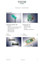
Product Overview Opto-electronic safety edge – OSE High safety Approved by the German employers' liability Modular system design High flexibility of the signaling unit Modular system design High system reliability Function Technical data Function Technical data
Open the catalog to page 3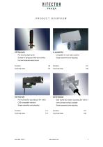
Pre-traveling light barrier compatible to most radio systems Suitable to safeguard wide door profiles Simple assembly and adjusting For low threshold wicket doors Technical data Technical data Pull-in protection according to EN 12453 Safe wicket door switch according EN 12453-1 OSE-compatible interface normal closed contact, testable Simple assembly and adjusting Simple assembly and adjusting Technical data Technical data
Open the catalog to page 4
SAFETY EDGES Cost efficiency Safety edges are used wherever moving edges Customers benefit from the simple installation, pose a hazard to people. The hazardous areas are short delivery times and simple logistics. protected by hollow rubber profiles. As soon as a person or object touches them, the sensing profile Mechanical design of a safety edge is deformed and the potentially hazardous move- As defined by the standards, a safety edge com- ment halted. prises three elements: the signaling element, sig- Safety edges are used in a variety of applications nal processing and signal output. in mechanical...
Open the catalog to page 5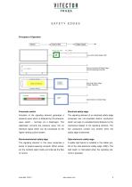
SAFETY EDGES Control Unit Output signal Pressure wave switch Pneumatic Safety Edge (DW) Electro-mechanical Safety Edge (positive-opening contacts) Resistanceor DiodeControl Unit Electrical Safety Edge (Diode, Resistor) Receiver Control Unit Opto-electronic Safety Edge Pneumatic switch Electrical safety edge Actuation of the signaling element generates a The signaling element of an electrical safety edge pressure wave which is detected by the pressure- comprises two non-insulated electric conductors wave switch – normally via a diaphragm. This which are kept at a predetermined distance by the...
Open the catalog to page 6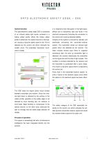
OPTO-ELECTRONIC SAFETY General function It is imperative that interruption of the light beam, The opto-electronic safety edge OSE is comprised effects due to extraneous light and faults in the of an infrared safety light barrier enclosed in a electrical components (including the connection to hollow rubber profile. When the hollow rubber the control unit) must be detected reliably. profile is deformed, the optical channel is interrupt- Integrity of the system is ensured by optically and ed, causing a dynamic safety signal to fail. This is detected by the control unit which interrupts the system....
Open the catalog to page 7
OPTO-ELECTRONIC SAFETY The design also yields advantages if a defect The advanced technology of the OSE yields a should arise: The safety edge can be replaced immediately Simple assembly during the technician's first visit. Repairs are there- High safety fore quick and inexpensive. High environmental stability Because defects in the safety edge are usually High flexibility. limited to the rubber profile, the OSE can be replaced quickly and easily keeping repair costs low For the customer, this not only means lower costs, and down time to a minimum. but also very high reliability and ready for...
Open the catalog to page 8
OPTO-ELECTRONIC SAFETY High resistance to weathering and aging High mechanical stability Large temperature range performance Existing profiles can be used if suitable (dependent upon geometry and material). The rubber profile can be produced to the customer's specific requirements. This permits a large variety of profile shapes (folding gates, The intelligence of the safety edge is located in the high-speed gates, etc.) while keeping profile Simple interface to the control unit can easily be integrated into the gate control Automatic adjustment of the transmitter power Due to the dynamic principle,...
Open the catalog to page 9
OPTO-ELECTRONIC SAFETY profile, as well as minor deformation caused by The simple modular design of the OSE system damage to the door leaf. This further enhances the allows users to install the safety edge themselves. availability of the safety edge. Only a few components are required and can be combined into a perfectly functioning safety edge without requiring any special tools or technical know-how. moving edge (l.g. bottom section) Control unit OSE-C Alu-C Profile The receiver responds to failure of the dynamic IR Receiver OSE-R Bumper OSE-B light beam by generating an error message which...
Open the catalog to page 10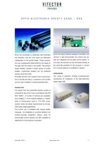
OPTO-ELECTRONIC SAFETY Since the transmitter is effectively self-controlled, Since the signal interface between transmitter and the actuation- and the over travel are effectively receiver is well documented, the control unit can independent of the profile length. These parame- also be integrated into the gate control system. In ters are consequently determined by the speed of this case, the sensors can be connected directly to the gate and the shape of the profile. The product the terminals provided for this purpose. A current range already includes a large variety of profile list of control...
Open the catalog to page 11
OPTO-ELECTRONIC SAFETY The safety edge can be installed directly on site, Installation of the opto-electronic safety edge (any because special tools and adhesives are not re- installed position) is a simple matter. Proceed as quired. The mechanical assembly should be exe- cuted by a skilled employee, the electrical connections by an electrical specialist. Attachment of the signaling element Regular maintenance of the machine, function and The ALU-2509 rail is meant for attaching the condition of the safety edge should be checked by safety profile. You have to drill holes into the a specialist...
Open the catalog to page 12All FRABA VITECTOR catalogs and technical brochures
 OSE-C 4024
3 Pages
 OSE-C 4524
3 Pages
 OSE-C 5024
3 Pages
 OSE-C 4024 (UL certified)
3 Pages
 OSE-C 1003
3 Pages
 OSE-C 1004
3 Pages
 OSE-C 1001
4 Pages
 OSE-C 2323
5 Pages
 OSE-C 2301
4 Pages
 OSE-C 2300
4 Pages
 OSE-C 2324
5 Pages
 SENSOR SOLUTIONS FOR DOORS
12 Pages
 OSE-B 5518
2 Pages
 OSE-B 7428
2 Pages
 OSE-B 8828
2 Pages
 OSE-B 3035
2 Pages
 OSE-B 2528
2 Pages
 OSE-B 2518
2 Pages
 OSE-B 2212
2 Pages
 OSE-S 1172
4 Pages
 OSE-S 1171
4 Pages
 OSE-S 1102
4 Pages
 OSE-S 1100
4 Pages
 OPC-S 4501
5 Pages
- Single-pole switch
- Photoelectric sensor
- Rotary electric switch
- Rectangular photoelectric sensor
- Light barrier
- Touch switch
- Plastic switch
- Safety light curtain
- LED photoelectric sensor
- Compact photoelectric sensor
- Red light photoelectric sensor
- Control switch
- Optical sensor
- T-shaped profile
- U-shaped profile
- Power switch
- Long-range photoelectric sensor