- Catalogs
- Fr. Sauter AG
- Transducer for differential pressure
Transducer for differential pressure
1 /2Pages

Transducer for differential pressure
1 /2Pages
Catalog excerpts

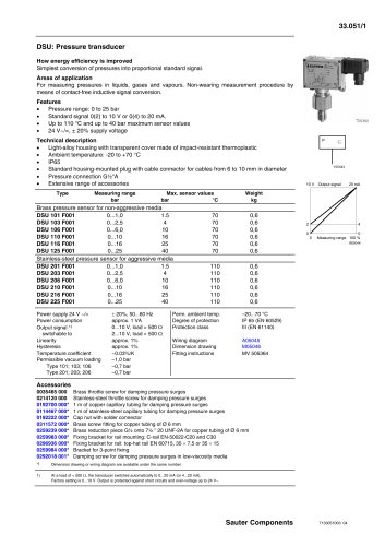
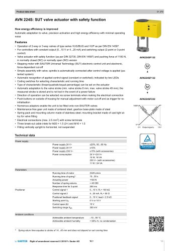
33.061/1 Sauter Components DSDU: Transducer for differential pressure How energy efficiency is improved Simplest conversion of pressure differences into proportional standard signal. Areas of application For measuring pressure differentials in liquids, gases and vapours. Non-wearing measurement procedure by means of contact-free inductive signal conversion. Features • Pressure differential measuring range: 0 to 6 bar • Standard signal 0(2) to 10 V or 0(4) to 20 mA • Up to 110 °C and up to 10 bar maximum sensor values • 24 V~/=, ± 20% supply voltage Technical description • Light-alloy housing with transparent cover made of impact-resistant thermoplastic • Ambient temperature: -20 to +70 °C • IP65 • Standard housing-mounted plug with cable connector for cables from 6 to 10 mm in diameter • Extensive range of accessories Operation The pressure difference in the sensor acts on a bourdon tube, thereby creating a force on the conversion spring. The resultant movement is converted into a standard electrical signal by an inductive distance sensor. The output signal rises in proportion to the pressure. Additional details Materials which come into contact with the medium are of stainless steel (material nos. 1.4104 and 1.4541) To protect the DSDU with a fuse, a fuse of at least 250 mA/250V should be used. Additional technical data Complies with:- EMC directive 2004/108/CE EN 61000-6-1/ EN 61000-6-2 EN 61000-6-3/ EN 61000-6-4 Covered by Art. 3.3. of the PED without safety function Y03197 PD 10 V 2 0 0 Measuring range 100 % Output signal 0 4 20 mA B05044 Type Measuring range Max. sensor values Weight Äp bar bar °C kg DSDU 100 F020 0...0,5 6 110 0,6 DSDU 101 F020 0...1 6 110 0,6 DSDU 103 F020 0...2,5 6 110 0,6 DSDU 106 F020 0...6 10 110 0,6 Power supply 24 V ~/= ± 20%, 50...60 Hz Perm. ambient temp. –20...70 °C Power consumption approx. 1 VA Degree of protection IP 65 (EN 60529) Output signal 1) 0...10 V, load > 500 Ù Protection class III (EN 61140) switchable to 2...10 V, load > 500 Ù Linearity approx. 1% Wiring diagram A05045 Hysteresis approx. 1% Dimension drawing M06967 Temperature coefficient ~0,03%/K Fitting instructions MV 505407 Permissible vacuum loading –0,7 bar Accessories 0190403 005* Brass connector with cap nut (Serto system), 2 pieces required 0292110 001* Two Rp 1/8 throttle screws for arresting pressure surges; stainless steel. 0296936 000* Bracket for rail: top-hat rail EN 60715, 35 × 7.5 or 35 × 15 0259984 000* Bracket for 3-point fixing *) Dimension drawing or wiring diagram are available under the same number 1) At a load of < 500 Ù, the transducer switches automatically to 0...20 mA (or 4...20 mA). Factory setting is 0...10 V. Output is protected against short circuits and over-voltage up to 24 V~. 7133061003 04
Open the catalog to page 1All Fr. Sauter AG catalogs and technical brochures
 SAUTER Catalogue
551 Pages
 HSC 120: Room humidistat
3 Pages
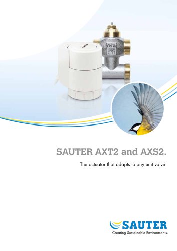 SAUTER AXT2 and AXS2.
8 Pages
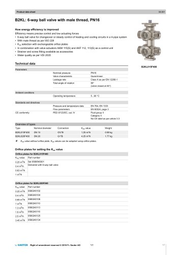
 Ball valve and actuator.
6 Pages
 SAUTER Valveco compact
8 Pages
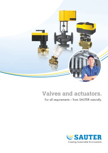 Valves and actuators.
32 Pages
 SAUTER vialoq AVM 100
2 Pages
 ASM 134: Damper actuator
4 Pages
 SAUTER flexotron ® 400
4 Pages
 EXG: Active potentiometer
2 Pages
 flexotron ® 2000
2 Pages
 SAUTER flexotron800
8 Pages
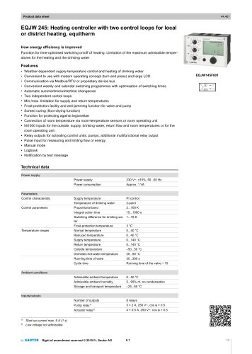 EQJW 24
8 Pages
 NRT 101
8 Pages
 Thermowells
6 Pages
 Indoor air quality
8 Pages
 SAUTER EGQ
4 Pages
 SAUTER equiflex ® NRT300
4 Pages
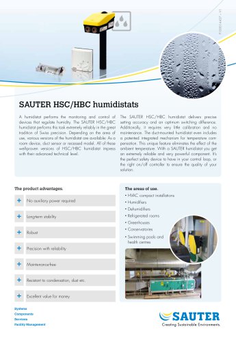 SAUTER HSC/HBC humidistats
2 Pages
 DSA: Pressure switch
4 Pages
 TFL 201
3 Pages
 TUC: Universal thermostat
5 Pages
 TLC
TLC2 Pages
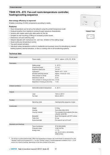 TSHK 670...67
3 Pages
 TSHK 621...643
4 Pages
 TSO, TSH: Room thermostat
4 Pages
 RAK: Universal thermostat
5 Pages
 SAUTER FACTS
28 Pages
 Pressure transducer
3 Pages
 Air-flow transducer
2 Pages


- Challenge Power Transmission valve
- Manual valve
- Control valve
- DC power supply
- Stainless valve
- Display module
- AC/DC power supply
- Ball valve
- Challenge Power Transmission temperature sensor
- Challenge Power Transmission pneumatic valve
- Threaded valve
- Regulating valve
- Flange valve
- LCD display panel
- Lever valve
- Challenge Power Transmission resistance temperature sensor
- Electric valve
- ISO valve
- Pressure limiter