- Catalogs
- Fr. Sauter AG
- TFL 201
TFL 201
1 /3Pages

TFL 201
1 /3Pages
Catalog excerpts
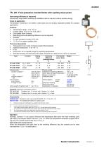
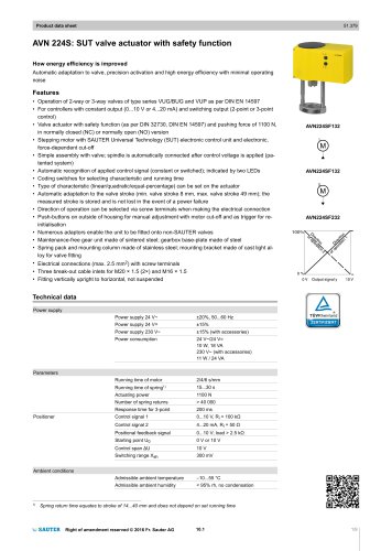
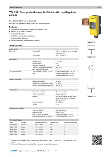
22.030/1 TFL 201: Frost-protection monitor/limiter with capillary-tube sensor How energy efficiency is improved Demand-led, large-scale monitoring of installation parts as required, without auxiliary energy. Areas of application Temperature monitoring in air heaters, water pipes and air ducting. Especially suitable for compact applications. Features • Temperature range: –5 to +15 °C • Contact rating: 4 mA, 6 V to 10 A, 250 V • Gold-plated silver contacts • Switching point and switching difference can be adjusted • Sealable • 2 s time constant in water at 0.5 m/s • 1.5, 3 or 6 m copper capillary tube Technical description • Transparent cover made of impact-resistant thermoplastic • Ambient temperature: –5 to +70 ° C • IP 65 • Active from 10 cm capillary length in switching temperature • Standard housing-mounted plug with cable connector for cables of 6 to 10 mm in diameter min. as gold contacts 2) min. Time constant in air 0.3 m/s in water 0.5 m/s Active length of capillary tube 3) Wiring diagram Factory setting Tolerance of switching difference Perm. temp. at head of instrument 4) Degree of protection Protection class XSd = fixed XSd = variable limiter Setting range Contact rating as silver contacts 1) Switching difference (Average values) K Permissible sensor temp. monitor limiter Dimension drawing Fitting instructions Declaration on materials Variants (otherwise as standard version) TFL 201 F101 TFL 201 F601 Capillary tube, 1.5 m long; with 3 holders, Xsd = fixed Capillary tube, 6.0 m long; with 5 holders, Xsd = fixed Accessories 0296936 000* Bracket for rail: top-hat rail EN 50022, 35 × 7.5 or 35 × 15 0303167 000* Five additional holders for capillary tube *) Dimension drawing or wiring diagram are available under the same number If under inductive load, take RC circuit into account. If the contacts are ever loaded higher than 160 mA, 50 V, the gold plating will be damaged. The contacts are then classed only as silver contacts, since they lose the characteristics of gold contacts. The monitor always reacts to the coldest place (minimum length is 10 cm). The head of the instrument must be fitted at a place which is warmer than that of the sensor. Operation Normally, contacts 1-3 are closed. Whenever the temperature falls below the lower switching point (set value), the contacts switch over from 1-3 to 1-2. When the temperature exceeds the upper switching point, the contacts switch back from 1-2 to 1-3. F021 limiter with mechanical lock When the temperature has again risen by the switching difference XSd, the contacts can be reset manually from 1-2 to 1-3 (
Open the catalog to page 1
22.030/2 TFL Explanation of type codes F Y (Function) 0 = Xsd = fixed 1 = Xsd = variable 2 = limiter Additional technical data CE conformity complies with: Low-Voltage Directive 2006/95/EC EMC Directive 2004/108/EC Technical notes Wiring diagram Monitor Dimension drawing Sauter Components RC circuit under inductive load For the optimum RC circuitry, refer to the specifications supplied by the manufacturers of the relays, contactors etc. If these are not available, the inductive load can be reduced by applying the following rule of thumb (not binding): • Capacity of the RC circuitry (µF) ≥ operating...
Open the catalog to page 2
Sauter Components Printed in Switzerland Right of amendment reserved © Fr. Sauter AG, CH-4016 Basle 7122030003 07
Open the catalog to page 3All Fr. Sauter AG catalogs and technical brochures
 SAUTER Catalogue
551 Pages
 HSC 120: Room humidistat
3 Pages
 SAUTER AXT2 and AXS2.
8 Pages
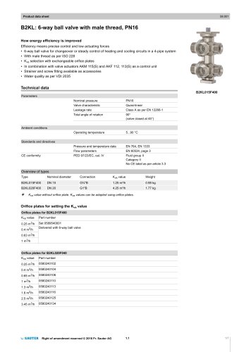
 Ball valve and actuator.
6 Pages
 SAUTER Valveco compact
8 Pages
 Valves and actuators.
32 Pages
 SAUTER vialoq AVM 100
2 Pages
 ASM 134: Damper actuator
4 Pages
 SAUTER flexotron ® 400
4 Pages
 EXG: Active potentiometer
2 Pages
 flexotron ® 2000
2 Pages
 SAUTER flexotron800
8 Pages
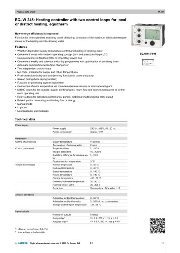 EQJW 24
8 Pages
 NRT 101
8 Pages
 Thermowells
6 Pages
 Indoor air quality
8 Pages
 SAUTER EGQ
4 Pages
 SAUTER equiflex ® NRT300
4 Pages
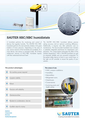 SAUTER HSC/HBC humidistats
2 Pages
 DSA: Pressure switch
4 Pages
 TUC: Universal thermostat
5 Pages
 TLC
TLC2 Pages
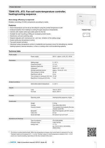 TSHK 670...67
3 Pages
 TSHK 621...643
4 Pages
 TSO, TSH: Room thermostat
4 Pages
 RAK: Universal thermostat
5 Pages
 SAUTER FACTS
28 Pages
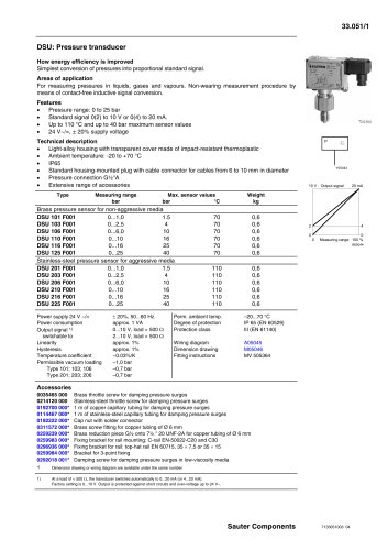 Pressure transducer
3 Pages
 Air-flow transducer
2 Pages


- Challenge Power Transmission valve
- Manual valve
- Power supply unit
- Control valve
- DC power supply
- Stainless valve
- Display module
- AC/DC power supply
- Ball valve
- Challenge Power Transmission temperature sensor
- Challenge Power Transmission pneumatic valve
- Threaded valve
- Regulating valve
- Flange valve
- LCD display panel
- Lever valve
- Challenge Power Transmission resistance temperature sensor
- Electric valve
- ISO valve
- Pressure limiter