- Catalogs
- Fr. Sauter AG
- TFC: Frost -protection monitor with capillary- tube sensor
TFC: Frost -protection monitor with capillary- tube sensor
1 /2Pages

TFC: Frost -protection monitor with capillary- tube sensor
1 /2Pages
Catalog excerpts
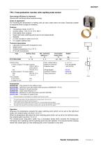
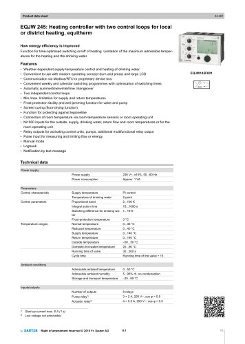
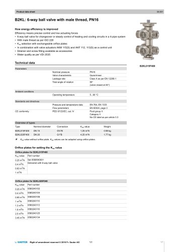
22.010/1 TFC: Frost-protection monitor with capillary-tube sensor How energy efficiency is improved Demand-led monitoring without external energy. Areas of application For monitoring the temperature in heating coils (air side), water drains and ducts. Especially suitable for equipment that is subject to vibrations. Features • Temperature range: 0 to15 °C • Contact rating: 1 mA, 6 V to 10 A, 400 V • Gold-plated silver contacts • Upper and lower switching points can be set independently • Sealable • 2 s time constant in water at 0.5 m/s • 6 m copper capillary tube Technical description • Light-alloy housing with transparent cover • Splash-proof • Ambient temperature: 0 to +70 °C • IP 54 with accessories Permissible sensor temp. °C Contact rating as silver contacts 2) for higher loading max. 10(2) A, 400 V~ 25 W, 250 V= min. 100 mA, 24 V as gold contacts 3) for lower loading max. 200 mA, 50 V min. 1 mA, 6 V Time constant in air 0.3 m/s 35 s in water 0.5 m/s 2s Perm. ambient temp. Degree of protection Protection class Wiring diagram Dimension drawing Fitting instructions Setting range Plug spanner for the setting screws Aluminium cover with window (with accessory 0259299 000 = IP 54) Bracket for off-wall mounting Cable screw fitting Pg 13.5 Bracket (for 3-point fixing when used with 0259189) Five holders for capillary tube Dimension drawing or wiring diagram are available under the same number The small values apply to the high setting points, the large values to the low ones. If under inductive load, take RC circuit into account. If the contacts are ever loaded higher than 200 mA, 50 V, the gold plating will be damaged. The contacts are then classed only as silver contacts, since they lose the properties of gold contacts. The head of the instrument must be fittes at a place which is warmer than that of the sensor. Operation Whenever the temperature exceeds the upper switching point (which can be set on the right-hand scale), the contacts switch over from 1-2 to 1-3. When the temperature falls below the lower switching point (which can be set on the left-hand scale), the contacts switch over from 1-3 to 1-2. The vibration-proof snap-action switch has a pre-loaded spring which prevents the change-over mechanism from operating until the switching point has been attained. This ensures that the contacts remain fully closed right up to the switching point, even if operation is very slow.
Open the catalog to page 1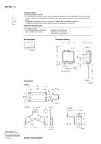
22.010/2 TFC Technical notes RC circuit under inductive load For the optimum RC circuitry, refer to the specifications supplied by the manufacturers of the relays, contactors etc. If these are not available, the following rule of thumb can be applied in order to reduce the inductive load:• Capacitance of the RC circuit (µF) is equal to or greater than the operating current (A). • Resistance of the RC circuit (Ω) is approx. equal to the resistance of the coil (Ω). B03772 Additional technical data CE conformity as per Low-Voltage Directive 2006/95/EC EMC Directive 2004/108/EC Wiring diagram Printed...
Open the catalog to page 2All Fr. Sauter AG catalogs and technical brochures
 SAUTER Catalogue
551 Pages
 HSC 120: Room humidistat
3 Pages
 SAUTER AXT2 and AXS2.
8 Pages
 Ball valve and actuator.
6 Pages
 SAUTER Valveco compact
8 Pages
 Valves and actuators.
32 Pages
 SAUTER vialoq AVM 100
2 Pages
 ASM 134: Damper actuator
4 Pages
 SAUTER flexotron ® 400
4 Pages
 EXG: Active potentiometer
2 Pages
 flexotron ® 2000
2 Pages
 SAUTER flexotron800
8 Pages
 EQJW 24
8 Pages
 NRT 101
8 Pages
 Thermowells
6 Pages
 Indoor air quality
8 Pages
 SAUTER EGQ
4 Pages
 SAUTER equiflex ® NRT300
4 Pages
 SAUTER HSC/HBC humidistats
2 Pages
 DSA: Pressure switch
4 Pages
 TFL 201
3 Pages
 TUC: Universal thermostat
5 Pages
 TLC
TLC2 Pages
 TSHK 670...67
3 Pages
 TSHK 621...643
4 Pages
 TSO, TSH: Room thermostat
4 Pages
 RAK: Universal thermostat
5 Pages
 SAUTER FACTS
28 Pages
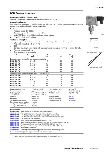 Pressure transducer
3 Pages
 Air-flow transducer
2 Pages


- Challenge Power Transmission valve
- Manual valve
- Power supply unit
- Control valve
- DC power supply
- Stainless valve
- Display module
- AC/DC power supply
- Ball valve
- Challenge Power Transmission temperature sensor
- Challenge Power Transmission pneumatic valve
- Threaded valve
- Regulating valve
- Flange valve
- LCD display panel
- Lever valve
- Challenge Power Transmission resistance temperature sensor
- Electric valve
- ISO valve
- Pressure limiter