- Catalogs
- Fr. Sauter AG
- Dew-point monitor and transducer
Dew-point monitor and transducer
1 /2Pages

Dew-point monitor and transducer
1 /2Pages
Catalog excerpts

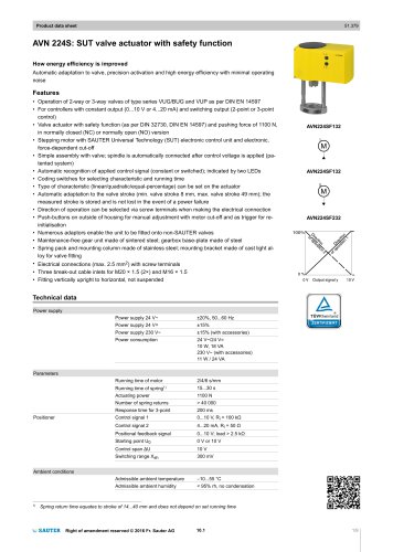
34.042 Sauter Components EGH 102: Dew-point monitor and transducer How energy efficiency is improved Effective protection against humidity damage and excessive cooling. Areas of application Protection against dew formation on chilled beams. Control system for a regulating unit using a holding relay, which interrupts the flow of cold water or raises the temperature of the cooling water. Features • Measurement is effected by a spring-loaded dew-point sensor • Active measured value acquisition • Versions with external sensor Technical description • Housing made of pure-white, flame-retardant thermoplastic (RAL 9010) • Holding relay with change-over contact • Screw terminals for wire of up to 1,5 mm² • Cable inlet for Pg 11 • Strap retainer for 10 to 100 mm ø pipe and heat-conducting paste are included in supply Operation The resistance of the dew-point sensor rises in accordance with the relative humidity. The resistance value is evaluated with the aid of the electronics unit and then (via a holding relay) used to control the change-over contacts. When power is applied, contacts 4-6 close as soon as the switching point is reached or exceeded. At the same time, contacts 4-5 open. If the switching point is undercut by the amount of the switching difference, contacts 4-6 open and contacts 4-5 close. In addition, there is an analogue output signal (Pin 3) available. If no power is applied, contacts 4-6 are closed and contacts 4- 5 are open. Engineering and fitting notes The monitor should be fitted to the supply pipe at its coldest place: the surface of the pipe should be rendered clean and bare, the heat-conducting paste applied sparingly, and the sensor fixed by tightening the strap (snap-shut mechanism). Y02859 H % Type Switching point %rh Sensor Measuring range %rh Power supply Weight kg EGH 102 F001 95 ± 4 on housing 70…85 24 V~/= 0,1 EGH 102 F101 95 ± 4 with cable 70…85 24 V~/= 0,1 Power supply 24 V~/= ± 20% Exposure to dew max. 30 min Switching difference fixed, approx. 5 %rh Ambient temperature 5...60 °C Power consumption max. 1 VA Degree of protection IP 40 (EN 60529) Change-over contacts 1) 1A, 24 V~/= Output signal Wiring diagram A09353 approx. 70...85 %rh 0...10 V, load > 10 kÙ Dimension drawing F001 M07664 Response time in still air:- F101 M10454 80 to 99 %rh max. 3 min Fitting instructions F001 MV 505732 99 to 80 %rh max. 3 min F101 MV 506037 1) When driving relays, contactors etc. with cos < 0,3, the use of an RC section in parallel to the coil is recommended. This reduces pitting of the contacts and prevents high-frequency interference impulses. XSd 6 B09444 5 4 95 %rh 10 V- Output signal 0 70 % r.h. 85 B06506 7134042003 04
Open the catalog to page 1All Fr. Sauter AG catalogs and technical brochures
 SAUTER Catalogue
551 Pages
 HSC 120: Room humidistat
3 Pages
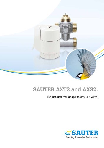 SAUTER AXT2 and AXS2.
8 Pages
 Ball valve and actuator.
6 Pages
 SAUTER Valveco compact
8 Pages
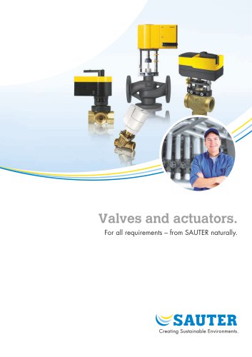 Valves and actuators.
32 Pages
 SAUTER vialoq AVM 100
2 Pages
 ASM 134: Damper actuator
4 Pages
 SAUTER flexotron ® 400
4 Pages
 EXG: Active potentiometer
2 Pages
 flexotron ® 2000
2 Pages
 SAUTER flexotron800
8 Pages
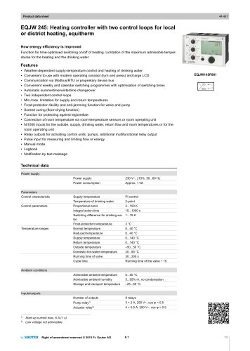 EQJW 24
8 Pages
 NRT 101
8 Pages
 Thermowells
6 Pages
 Indoor air quality
8 Pages
 SAUTER EGQ
4 Pages
 SAUTER equiflex ® NRT300
4 Pages
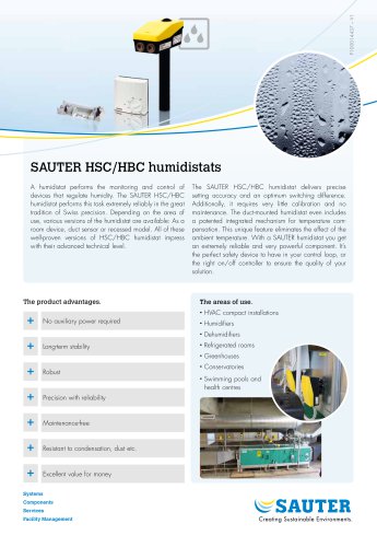 SAUTER HSC/HBC humidistats
2 Pages
 DSA: Pressure switch
4 Pages
 TFL 201
3 Pages
 TUC: Universal thermostat
5 Pages
 TLC
TLC2 Pages
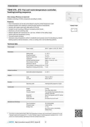 TSHK 670...67
3 Pages
 TSHK 621...643
4 Pages
 TSO, TSH: Room thermostat
4 Pages
 RAK: Universal thermostat
5 Pages
 SAUTER FACTS
28 Pages
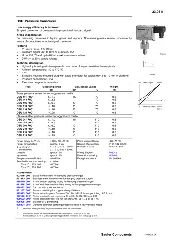 Pressure transducer
3 Pages
 Air-flow transducer
2 Pages


- Challenge Power Transmission valve
- Manual valve
- Control valve
- DC power supply
- Stainless valve
- Display module
- AC/DC power supply
- Ball valve
- Challenge Power Transmission temperature sensor
- Challenge Power Transmission pneumatic valve
- Threaded valve
- Regulating valve
- Flange valve
- LCD display panel
- Lever valve
- Challenge Power Transmission resistance temperature sensor
- Electric valve
- ISO valve
- Pressure limiter