- Catalogs
- Forbo Siegling GmbH
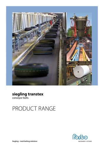
- siegling transtex
- Company
- Products
- Catalogs
- News & Trends
- Exhibitions
siegling transtex
1 /20Pages

siegling transtex
1 /20Pages
Catalog excerpts
conveyor belts conveying systems 11 Dimensioning force-dependent take-up systems conveying systems 15 Calculation example for unit goods conveying MOVEMENT SYSTEMS Siegling - total belting solutions
Open the catalog to page 1
This brochure contains advanced equations, figures and recommendations, based on our longstanding experience. Results calculated can however differ from our calculation program B_Rex (free to download from the Internet at www.forbo-siegling.com). These variations are due to the very different approaches taken: while B_Rex is based on empirical measurements and requires a detailed description of the machinery, the calculation methods shown here are based on general, simple physical equations, supplemented by certain factors that include a safety margin. In the majority of cases, the safety margin...
Open the catalog to page 2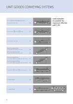
Unit goods conveying systems m = lT . Weight of conveyed goods per metre FU = µR . g . (m + mB + mR ) Direction conveyed upward: FU = µR . g (m + mB + mR ) + g . m . sin α Direction conveyed downward: FU = µR . g (m + mB + mR ) – g . m . sin α Direction conveyed upward: FU = µT . g ( m + mB ) + µR . g ( mB + mR ) + g . m . sin α 2 2 Direction conveyed downward: FU = µT . g ( m + mB ) + µR . g ( mB + mR ) – g . m . sin α 2 2 Load examples to establish the
Open the catalog to page 5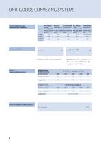
Lagged drum not recommended Minimum diameter of the drive drums dA
Open the catalog to page 6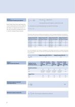
Checking the Transtex type selected if the value Jn_ is larger than C2, bo Note: If belts have been perforated, b0 must be reduced by the total width of the holes at a typical cross section. In the case of extreme temperatures, the C2 factors change. Please enquire. a stronger belt type (with a higher ki% value) must be used. C2 indicates the max. permitted belt pull per unit width for the belt type: The product data sheets list details on the relaxed k1% value. If example calculations and rough estimates without a data sheet are required, the following assumptions can be made (but not guaranteed):...
Open the catalog to page 7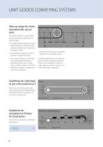
Unit goods conveying systems Take-up range for screwoperated take-up systems The following factors must be taken into account when establishing the take-up range: 1. The approximate magnitude of elon gation at fitting ε of the belt, resulting from the belt load. To establish ε, see pages 7 and 8. 2. The production tolerances (Tol) of the belt as regards the length. 3. Any external influences that might necessitate greater elongation (tensioning) than usual, or might require a safety margin Z, such as for example the impact of temperature, stop-and-go operation. Guidelines for shaft load at rest...
Open the catalog to page 8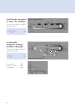
Guidelines for elongation at fitting ε for tail drives Tail drive in steady state forces The minimum elongation at fitting for return side drives is: Guidelines for elongation at fitting ε for return-side drives The minimum elongation at fitting for operating head drives is: Return side drive in steady state K for head drives K for return-side drives K for tail drives
Open the catalog to page 9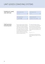
Typical drive drum p = 180° Typical snub roller p = 60° Typical drive drum p * 180° Shaft load when tensioning belts Tension members made of synthetic materials display significant relaxation behaviour. As a result, the relaxed k1% value is taken as a basis for calculating belts in line with ISO 21181. It describes the probable long-term force-elongation properties of the belt material that has been subjected to stress due to deflection and load change. This produces the calculation force Fw. This implies that higher belt forces Fwinitiai will occur when tensioning the belt. They will have to...
Open the catalog to page 10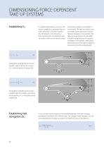
Dimensioning force-dependent take-up systems Establishing FR In weight-loaded take-up systems, the tension weight must generate the minimum belt pull F2 to achieve perfect grip of the belt on the drive drum (spring, pneumatic and hydraulic takeup systems work on a similar principle). The tension weight must be able to move freely. The take-up system must be installed behind the drive section. Reverse operation is not possible. The take-up range depends on the effective pull, the tensile force F2 required, elongation of the belt ΔL, the production tolerance Tol, the safety margin for tensioning...
Open the catalog to page 11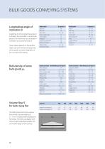
Goods conveyed Bulk density pS [103 kg/m3] Longitudinal angle of inclination 6 Guidelines for the longitudinal angle of inclination 5 permissible in various bulk goods. The machinery's actual angle of inclination a must be less than 5. These values depend on the particle shape, size and mechanical properties of the goods conveyed, regardless of any conveyor belt coating. The table shows the hourly volume flow (m3/h) at a belt velocity of v = 1 m/s. Conveyor belt lying flat and horizontal. The belt is equipped with 20 mm high longitudinal profiles T20 on the belt edges of the top face.
Open the catalog to page 12
Under real world conditions, the theoretical values for volume flow are hardly ever reached as they only apply to horizontal belts with perfectly even loads. Uneven loads and the properties of the goods conveyed can decrease the amount by approx. 30 %. In inclined conveying, the theoretical quantity of goods conveyed is slightly less. It is calculated by applying the factor C6 which depends on the conveying angle a. Additional effective pull, for example from scrapers and cleaning devices, is taken into account by including the factor Q.
Open the catalog to page 13
Bulk goods conveying systems Rolling resistance for support rollers f Establishing the mass of goods conveyed m Establishing the effective pull FU Support roller pitches f = 0.025 for roller bearings f = 0.050 for slide bearings Calculation as for unit goods The support roller pitch depends on the belt pull and the masses. The following equation is used to calculate it: If maximum sag of 1 % is permitted, (i.e. yB = 0.01 l0) Recommendation l0 max ≤ 2b0 lu = Support roller pitch on upper side in mm = Maximum conveyor belt sag in mm = Belt pull in the place concerned in N = Weight of goods conveyed...
Open the catalog to page 14All Forbo Siegling GmbH catalogs and technical brochures
 Wood based panels manufacture
12 Pages
 siegling transtex (2025)
12 Pages
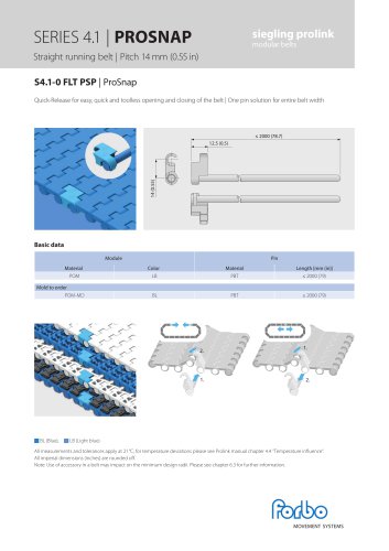 S4.1-0 FLT PSP
1 Page
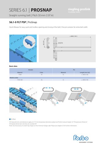 S6.1-0 FLT PSP
1 Page
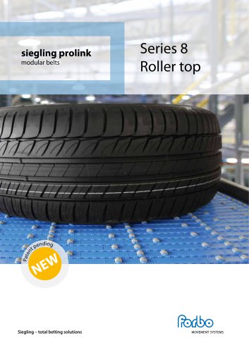 Series 8 Roller top 2025
2 Pages
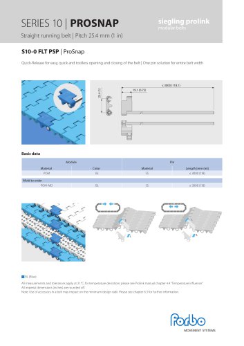 SERIES 10 | PROSNAP
1 Page
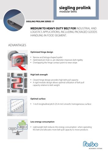 SIEGLING PROLINK SERIES 17
2 Pages
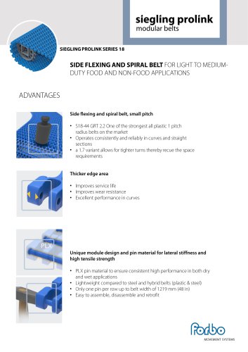 SIEGLING PROLINK SERIES 18
2 Pages
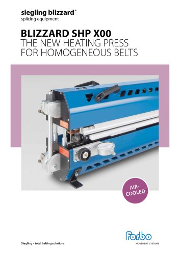 BLIZZARD SHP X00
8 Pages
 FLIGHTS AND SIDEWALLS
6 Pages
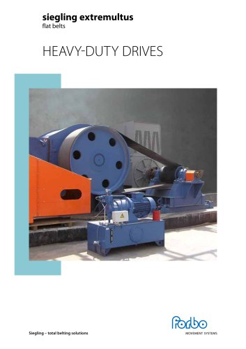 Heavy-duty drive 2025
4 Pages
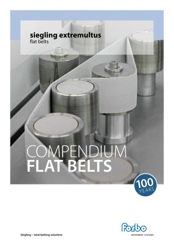 Compendium FLAT BELTS 2025
128 Pages
 TRANSILON ECOFIBER
2 Pages
 Series 11
10 Pages
 Series 10
14 Pages
 Series 9
11 Pages
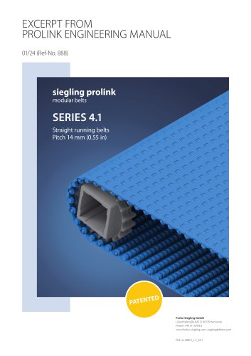 Series 4.1
10 Pages
 Series 5
24 Pages
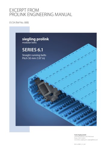 SERIES 6.1
19 Pages
 Series 7
13 Pages
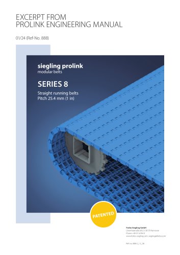 SERIES 8
19 Pages
 ECOFIBER
2 Pages
 AMP MISER
8 Pages
 Datasheet 900006
4 Pages
 Siegling Belting – Meshbelts
2 Pages
 timing belts
16 Pages
 Liver roller belts
2 Pages
 Heavy-duty drive
4 Pages
 Modular Belts
28 Pages
 Conveyor and processing belts
16 Pages
 Siegling total belting solutions
12 Pages
 Compendium FLAT BELTS
128 Pages
 Series 8 Roller top
2 Pages
 Marmoleum Tile 2.0 and 2.5mm
51 Pages
 MARMOLEUM STRIATO AND WALTON
48 Pages
 Marmoleum 2.0 and 2.5 mm
54 Pages
 Marmoleum Decibel
44 Pages
 Siegling Belting – Sports
4 Pages
 Siegling Belting – Automotive
12 Pages
 Siegling Belting – Wood
12 Pages
 Siegling Belting – Tobacco
8 Pages
 Siegling Belting – Airports
12 Pages
 Siegling Belting – Food
32 Pages
 Siegling Belting – Logistics
20 Pages
 Siegling Belting – Tire Industry
12 Pages
 Serie 14
5 Pages
 Serie 13
6 Pages
 Serie 8
16 Pages
 Serie 6.1
16 Pages
 Serie 4.1
10 Pages


Archived catalogs
 Series 3
10 Pages
 Series 2
12 Pages
 Prolink Engineering Manual
282 Pages
 Standard Product Range
16 Pages
 Series 1
11 Pages
 Round Belts
6 Pages
- Industrial press
- Transport rail conveyor
- Belt conveyor
- Horizontal conveyor
- AMOT transmission belt
- AMOT industrial belt
- Electric drive conveyor
- AMOT plastic conveyor belt
- Rubber strip
- Inclined conveyor
- AMOT industrial conveyor belt
- Work conveyor
- Electric press
- AMOT industrial belt
- AMOT flush grid conveyor belt
- Modular conveyor
- AMOT plastic belt
- AMOT modular conveyor belt