- Catalogs
- Foerster Instruments
- Sensor system T leaflet
- Products
- Catalogs
- News & Trends
- Exhibitions
Sensor system T leaflet

Sensor system T leaflet
Catalog excerpts

DEFECTOTHERM Sensor system T 60 2.863 Sensor system T 60 with guide units Sensor system for hot wire testing up to +1200 °C For wire or rod diameters from around 5 to 60 mm Coil carrier T 60 for water-cooled LMDTherm coils Online testing directly in the rolling line Designed for maximum production speeds Fast dimension change in the line Fast conversion for line operation “Without testing” Full functionality without sliding table Operator control end can be adapted locally without special tools
Open the catalog to page 1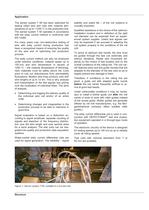
Application The sensor system T 60 has been optimized for testing rolled wire and rods with material temperatures of up to +1200 °C in the production line. The sensor system T 60 operates in accordance with the eddy current method in conformity with EN 12084. For many years now, non-destructive testing of wire with eddy current during production has been a recognized means of ensuring the quality of the wire and of optimizing the production process. The eddy current method can also be employed under extreme conditions: material speed up to 150 m/s and wire temperature in excess of 1000 °C – the...
Open the catalog to page 2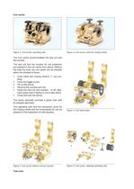
Coil carrier Figure 2: Coil carrier, operating side Figure 3: Coil carrier, ports for cooling media The Coil carrier accommodates the test coil and the nozzles. The test coil and the nozzles for coil protection are inserted in the coil carrier from above. Without the need for tools, the coil carrier can be retooled within the shortest of times: Undo cable and cooling medium coil coupling. Undo the toggle screw. Tilt up the stirrup. Remove the nozzles and coil. Insert the new coil and nozzles – or NT (Not- Test) guide tube if testing is not to take place. Close and lock the stirrup. The owner...
Open the catalog to page 3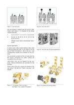
Figure 7: Test coils size I Figure 8: Test coils size II Hot wire testing is realized with the proven LMDTherm coils, sizes I + II, selected for the tested material diameter. I: (7), 8, 9, 10, 11, 12, 13, 15, 17, 20, 23 mm II: 26, 29, 32, 35, 38, 41, 44, 47, 50, 53, 56, 59, 62, 65 mm (Please inquire about intermediate dimensions) Figure 9: Test coils size III (special application) Special application: In some cases, eddy current testing is also used to test hot pipes and rods. A coil holder III for the use of Therm coil sizes III – 65 to 125 mm – and corresponding nozzles are available for this...
Open the catalog to page 4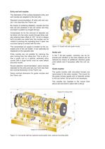
Entry and exit nozzles Figure 12: Guide unit with guide nozzle Guide unit The diameters of the surface-hardened entry and exit nozzles are adapted to the test coils. Standard recommendation: Ø entry and exit nozzle 1 mm less than the Therm coil. By means of centering adapters, nozzles and the test coil are centered in the coil carrier and they are fixed in position by hinged stirrups. Compressed air for the removal of deposits can be blown into the entry nozzle through three radially entering holes offset at 120°. As air is always fed to at least one radial hole, the nozzles can be rotated to...
Open the catalog to page 5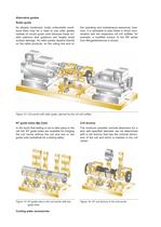
Alternative guides Roller guide As already mentioned, under unfavorable conditions there may be a need to use roller guides instead of nozzle guide units because these enable optimum wire guidance and largely avoid surface damage. As roller guides depend directly on the rolled products, on the rolling line and on the operating and maintenance personnel, however, it is advisable to plan these in direct coordination with the respective roll mill outfitter; for example, a modified version of the SR series from Morgardshammar is shown. Figure 14: Coil carrier with roller guide, planned by the roll...
Open the catalog to page 6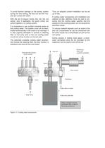
To avoid thermal damage on the sensor system during hot wire testing, the test coil and the nozzles are cooled with water. With the aid of plug-in hoses, the coil, the coil carrier, and, if applicable, the guide unit(s) are joined together in a cooling system. It is imperative to use purified industrial water as the cooling water. The system must not be deactivated automatically in the event of an average. It is also urgently advisable to provide a cleaning filter on the entry side of the coil cooling water circuit and a flow monitor on the exit side. The optionally available cooling water accessories...
Open the catalog to page 7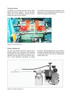
Test piece sensor Controlled by an infrared test piece sensor fitted before the sensor system T 60, the dynamic signal lock of the electronic testing unit suppresses the start and end signals. The infrared test piece sensor is installed in any position up to 10 m ahead of the test coil with a direct line of sight to the test piece. Figure 18: Test piece sensor Powder marking unit On warm test material, flaws are marked with a powder marking unit, if necessary. Flaw markings are possible up to test speeds of around 15 m/s. Attention must be paid to the fact that the intensity of paint application...
Open the catalog to page 8
Electronic testing unit • DEFECTOMAT DS (see Leaflet DEFECTOMAT® DS 2.815) Connecting cables Connecting cables as detailed in the cable overview diagram are needed to establish the electrical connection between the testing and evaluation unit and the sensor system with the test piece sensor and marking unit. Figure 21 shows the layout that is recommended. As the electronic test unit does not feature any operator controls whatever, it can be accommodated in a protective housing in the proximity of the testing location and will only require accessibility for servicing. The advantage of this arrangement...
Open the catalog to page 9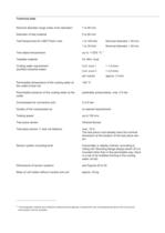
Technical data Nominal diameter range (clear inner diameter) 7 to 65 mm Diameter of test material 5 to 60 mm 1 to Test frequencies for LMD-Therm coils 100 kHz Nominal diameter < 29 mm 1 to 30 kHz Nominal diameter > 29mm Test object temperature up to +1200 °C 1 Testable material Fe, NFe, Aust. Coil size I > 1,5 l/min Coil size II > 2,5 l/min Cooling water requirement (purified industrial water) per nozzle approx. 2 l/min Permissible temperature of the cooling water at the outlet of test coil +60 °C Permissible pressure of the cooling water at the outlet preferably pressureless, max. 0,5 bar Compressed...
Open the catalog to page 10All Foerster Instruments catalogs and technical brochures
 STATOGRAPH® DS 6.440
12 Pages
 DEFECTOMAT
8 Pages

Archived catalogs
 Probe Catalog
26 Pages
 STATOGRAPH TOUCH PROBES leaflet
14 Pages
 MAGNATEST ECM CE leaflet
6 Pages
 MAGNATEST ECM leaflet
6 Pages
 MAGNATEST brochure
4 Pages
 CIRCOFLUX brochure
6 Pages
 CIRCOSCAN leaflet
20 Pages
 CIRCOGRAPH DS leaflet
12 Pages
 DEFECTOMINI leaflet
8 Pages
 Sensor system M leaflet
26 Pages
 Sensor system P leaflet
14 Pages
 Sensor system H leaflet
12 Pages
 DEFECTOMAT ECM leaflet
6 Pages
 DEFECTOMAT DI brochure
4 Pages
 DEFECTOMAT CI brochure
4 Pages
 DEFECTOMAT DS
14 Pages


- Monitoring software solution
- Inspection system
- Visualization software solution
- Leak tester
- Test software
- Automatic inspection system
- Industrial control system
- Magnetic sensor
- Digital control system
- Surface measuring machine
- Flaw detector
- Electrical appliance tester
- Industrial surface measuring machine
- Conductivity meter
- Surface inspection system
- Leakage tester
- Inspection device
- Demagnetizer
- Portable conductivity meter
- Workpiece demagnetizer