
Catalog excerpts
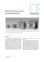
DEFECTOTEST® Sensor systems M 2.850/2.851/2.852/2.853 Figure 1: Sensor systems M 40, M 90, M 170 and M 240 Application In the majority of cases when using the eddycurrent method for non-destructive flaw testing, it is necessary to magnetize cold, ferromagnetic and austenitic semifinished parts. For this reason the type M* sensor systems have been developed as a principal component of the DEFECTOTEST system. Their main area of application is continuous throughput testing of pipes, rods and wires with circular or profiled cross-sections. This is done in conjunction with a DEFECTOMAT® electronic test and evaluation unit. The type M sensor systems cover the material diameter range from approx. 1.0 to 240 mm. Test material temperatures up to +80 °C are permitted. The M sensor systems are integrated into conveying equipment suited to the test requirements. The material to be checked passes centrically through the sensor system, and is thereby nondestructively tested. The M sensor systems also allow “Not Fe-semi-finished products” to be tested at any time. However, in this case it is not necessary to magnetize the test piece. Type H sensor systems are available especially for testing “Not Fe-semi-finished products” by the continuous passage method. * M = Magnetization
Open the catalog to page 1
2.850/2.851/2.852/2.853 2 Method of operation In type M eddy-current sensor systems the electrical testing signals are generated by the electromagnetic interaction set up between the test piece and testing coils as the test piece passes through. The physical method of operation is in accordance with German Standard DIN 54 140. For most testing tasks type LMD1 through-type coil using multi-differential circuitry are installed in the type M sensor systems. If higher testing frequencies are required, then HMD2 throughtype coils are used. With these differential coils a comparison is made with...
Open the catalog to page 2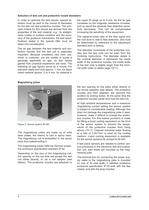
3 2.850/2.851/2.852/2.853 Selection of test coil and protective nozzle diameters In order to optimize the test results, special attention must be paid to the choice of diameters for the test coil and protective nozzles. The principal criteria for this choice are derived from the properties of the test material, e.g., its straightness, ovality or surface condition and the accuracy of the guidance mechanism; the test specifications stated in the special offer must be taken into consideration. The air gap between the test material and protective nozzles and the test coil is especially...
Open the catalog to page 3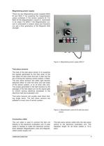
2.850/2.851/2.852/2.853 4 Magnetizing power supply There are two Magnetizing power supplies MAG M and MAG F for powering the magnetization yokes contained in the sensor systems M. For MAG M the Magnetization current is switchable in six steps. For MAG F the Magnetization current is switchable in sixteen steps and therefore you get a finer graduation of the Magnetic field strength. Figure 3: Magnetizing power supply MAG F Test piece sensors The task of the test piece sensor is to suppress the signals generated by the free ends of the test object as they enter and exit; it also has the job of...
Open the catalog to page 4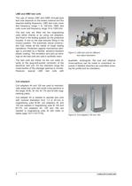
5 2.850/2.851/2.852/2.853 LMD and HMD test coils Figure 5: LMD test coils for different test object diameters The use of series LMD and HMD through-type test coils depends on the tested material and the required testing frequency: LMD test coils cover test frequency range 1 to 100 kHz, HMD test coils cover test frequency range 10 to 1000 kHz. The test coils are fitted into the magnetizing yoke either directly or by using coil adapters, and fixed in the testing position by the protective nozzles. A slot on the side ensures fitting in the correct position. The extremely robust construction...
Open the catalog to page 5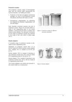
2.850/2.851/2.852/2.853 6 Protective nozzles The protective nozzles made of ferromagnetic steel with the internal width representing the nominal diameter, are fulfilling two tasks: • Protection of the test coil against mechanical damage, e.g. due to out-of-tolerance curved test pieces, and those with badly cut ends • Homogenous magnetization by optimizing the magnetic flux between magnetization coil and test object. Each diameter increment requires one pair of protective nozzle. These are mounted either directly in the magnetizing yoke, or via nozzle adapters. Locking levers fix them in...
Open the catalog to page 6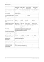
7 2.850/2.851/2.852/2.853 Technical Data Sensor system M 40 Sensor system M 90 Sensor systems M 140 and M 170 Sensor system M 240 Nominal diameter range (nominal diameter of the associated test coil) 1.2 to 44 mm Ø 1.2 to 100 mm Ø 1.2 to 150 mm Ø resp. 1.2 to 180 mm Ø 1.2 to 250 mm Ø Test coil diameter see table page 10/11 Test frequency range for LMD test coils 1 to 100 kHz 1 to 30 kHz Test frequency range for HMD test coils 1 to 1000 kHz Maximum field strength at test piece 295 kA/m 338 kA/m 298 kA/m 284 kA/m Largest test object cross section for saturation magnetization approx. 800 mm2,...
Open the catalog to page 7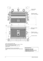
9 2.850/2.851/2.852/2.853 Main dimensions Magnetizing yoke M 40 Magnetizing yoke M 90 Magnetizing yoke M 140 + M 170 Magnetizing yoke M 240 Liquid cooling equipment data: Max. water pressure 6 bar. Water flow approx. 3 l/min. Use only cleaned industrial water. Coolant water connection for hose with 9 mm internal width. Magnetizing yoke shown in plane elevation no guide locking, cable holder and liquid cooling equipment Protective nozzle and/or nozzle adapter Liquid cooling equipment LMD test coil and/or coil adapter Protective nozzle and/or nozzle adapter Test piece sensor
Open the catalog to page 9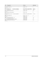
13 2.850/2.851/2.852/2.853 Pos. Designation Part-No. Mass [kg] 1 Coil cable 10 m 2.899.51-1110 3 2 LMD test coil 1.2 to 44 mm nominal-Ø HMD test coil 1.2 to 44 mm nominal-Ø 2.891.30-0012 to 2.891.30-0440 2.891.31-1012 to 2.891.31-1440 approx. 1 approx. 1 5 Magnetizing yoke M 40 2.850.01-1002 55 6 Liquid cooling equipment 2.850.01-1901 4 7 Protective nozzle 1.2 to 44 mm nominal-Ø 2.850.01-2012 to 2.850.01-2440 1 to 2.5 12 Yoke cable 10 m 2.899.11-1210 or 2.899.01-1210 3 13 Test piece sensor, left or Test piece sensor, right or Double test piece sensor (Option) 2.850.01-6020 2.850.01-6030...
Open the catalog to page 13All Foerster Instruments catalogs and technical brochures
-
STATOGRAPH® DS 6.440
12 Pages
-
DEFECTOMAT
8 Pages
Archived catalogs
-
Probe Catalog
26 Pages
-
STATOGRAPH TOUCH PROBES leaflet
14 Pages
-
MAGNATEST ECM CE leaflet
6 Pages
-
MAGNATEST ECM leaflet
6 Pages
-
Fine Wire Inspection System
1 Pages
-
MAGNATEST brochure
4 Pages
-
CIRCOFLUX brochure
6 Pages
-
CIRCOSCAN leaflet
20 Pages
-
CIRCOGRAPH DS leaflet
12 Pages
-
DEFECTOMINI leaflet
8 Pages
-
Sensor system T leaflet
15 Pages
-
Sensor system P leaflet
14 Pages
-
Sensor system H leaflet
12 Pages
-
DEFECTOMAT ECM leaflet
6 Pages
-
DEFECTOMAT DI brochure
4 Pages
-
DEFECTOMAT CI brochure
4 Pages
-
DEFECTOMAT DS
14 Pages


