
- Catalogs
- Focus LCDs
- E43GB-I-MW405-C

E43GB-I-MW405-C
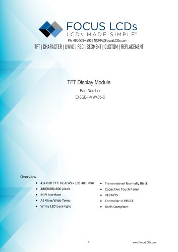
E43GB-I-MW405-C
The document provides detailed specifications and handling instructions for the 4.3-inch TFT Display Module, part number E43GB-I-MW405-C. Key features include a resolution of 480(RGB)x800 pixels, MIPI interface, wide viewing angles, and a capacitive touch panel. The module is RoHS compliant and operates within a temperature range of -20 to +70°C.
- Display: 4.3-inch TFT, 480x800 pixels, 16.7M colors, transmissive/normally black mode.
- Interface: MIPI 2 LINE, ILI9806E controller IC.
- Touch Panel: G+G structure, GT911 controller IC, I2C interface.
- Backlight: White LED, 410 NITS brightness, 50,000-hour lifetime.
- Dimensions: 62.4(W) x 105.4(H) x 3.93(D) mm.
- Contrast Ratio: 1000-1500.
- Response Time: 35-40 ms.
- Viewing Angle: 70-80 degrees in all directions.
- Supply Voltage: 3.3V for VCI, 5V maximum for digital supply.
- Backlight Current: 40 mA typical.
- Avoid physical shock and static discharge.
- Do not disassemble the module or expose it to high temperatures and humidity.
- Use appropriate cleaning agents and avoid direct sunlight during storage.
The document provides comprehensive technical details and guidelines for the safe handling and operation of the TFT display module, ensuring optimal performance and longevity.
Catalog excerpts
TFT | CHARACTER | UWVD | FSC | SEGMENT | CUSTOM | REPLACEMENT TFT Display Module Part Number E43GB-I-MW405-C • Transmissive/ Normally Black • Capacitive Touch Panel • MIPI Interface • RoHS Compliant
Open the catalog to page 1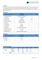
Description This is a color active matrix TFT (Thin Film Transistor) LCD (Liquid Crystal Display) that uses amorphous silicon TFT as a switching device. This model is composed of a transmissive type TFT-LCD Panel, driver circuit, capacitive touch panel and backlight unit. The resolution of the 4.3" TFT-LCD contains 480x800 pixels and can display up to 65K/262K/16.7M colors.
Open the catalog to page 2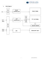
FOCUS LCDs Block Diagram TOUCH CONTROLLER TOUCH PANEL GATE DRIVER Input Signal SOURCE DRIVER LEDA LEDK BACKLIGHT UNIT
Open the catalog to page 3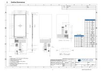
Outline Dimensions LCDs MADE SIMPLE®
Open the catalog to page 4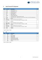
3. Input Terminal Pin Assignment NO. I: Input, O: Output, P: Power I: Input, O: Output, P: Power
Open the catalog to page 5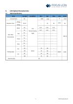
4. LCD Optical Characteristics4.1 Optical Specifications_ www.FocusLCDs.com
Open the catalog to page 6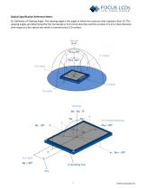
FOCUS LCDs Optical Specification Reference Notes: (1) Definition of Viewing Angle: The viewing angle is the angle at which the contrast ratio is greater than 10. The viewing angles are determined for the horizontal or 3,9 o'clock direction and the vertical or 6,12 o'clock direction with respect to the optical axis which is normal to the LCD surface.
Open the catalog to page 7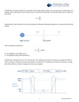
FOCUS LCDs (2) Definition of Contrast Ratio (Cr): measured at the center point of panel. The contrast ratio (Cr) measured on a module, is the ratio between the luminance (Lw) in a full white area (R=G=B=1) and the luminance (Ld) in a dark area (R=G=B=0). Cr = (3) Definition of transmittance (T%): The transmittance of the panel including the polarizers is measured with electrical driving. Io = the brightness of the light source. It = the brightness after panel transmission (4) Definition of Response Time (Tr, Tf): The rise time ŢTr’ is defined as the time for luminance to change from 90% to 10%...
Open the catalog to page 8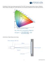
FOCUS LCDs (5) Definition of Color Gamut: Measuring machine CFT-01. NTSC’s Primaries: R(x,y,Y),G(x,y,Y), B(x,y,Y). FPM520 of Westar Display Technologies, INC., which utilized SR-3 for Chromaticity and BM-5A for other optical characteristics. (6) Definition of Optical Measurement Setup:
Open the catalog to page 9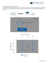
FOCUS LCDs (6) Optical Measurement Setup Continued: The LCD module should be stabilized at a given temperature for 20 minutes to avoid abrupt temperature change during measuring. In order to stabilize the luminance, the measurement should be executed after lighting backlight for 20 minutes.
Open the catalog to page 10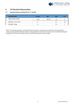
5. TFT Electrical Characteristics5.1 Absolute Maximum Rating (Ta=25 °C, VSS=0V) Characteristics NOTE: If the absolute maximum rating of the above parameters is exceeded, even momentarily, the quality of the product may be degraded. Absolute maximum ratings specify the values which the product may be physically damaged if exceeded. Be sure to use the product within the range of the absolute maximum ratings.
Open the catalog to page 11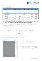
LCDs SIMPLE® 5.2 LED Backlight Characteristics Item The back-light system is edge-lighting type with 8 chips White LED. Note 1: LED lifetime (Hr) can be defined as the time in which it continues to operate under the condition: Ta=25 ±3 °C, typical IL value indicated in the above table until the brightness becomes less than 50%. Note 2: The "LED lifetime" is defined as the module brightness decrease to 50% original brightness at Ta=25°C and IL=40mA. The LED lifetime could be decreased if operating IL is larger than 40mA. The constant current driving method is suggested. B/L Circuit Note 3: Luminance...
Open the catalog to page 12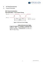
Figure 115 DSI Clock Channel Timing Tabic 44 DSI Clock Channel liming Pnra iiHra 12.5 Note. Ul — (JIisjta- UIhatf}
Open the catalog to page 13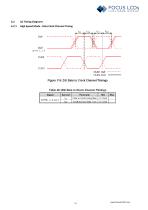
AC Timing DiagramsHigh Speed Mode - Data Clock Channel Timing DuP Data to Clock Setup time Clock lo Data Hold I me
Open the catalog to page 14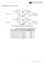
6.2.2 High Speed Mode - Rise and Fall Timing(wmiTA & V Hafeienca fri niflfcrmiial Ckx L ! 11 ■ > j4 & V Rf Eti-c lx l' far DiffcrnilijL JJilii kunth Fiyuro 117 Ri&sand Fail Timiriya on Clock mid Data Channels Table 46 Rise and Fal Timinyt on Clock and Dala. Channels
Open the catalog to page 15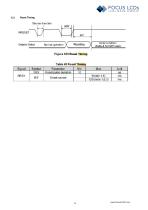
Shaft* I'ihii Oiiplay Status Namna □pe-alicm ^ nstetthg Figure !Q3 Reset Timing Table 4Q Reset Timing
Open the catalog to page 16
7. Cautions and Handling Precautions 7.1 Handling and Operating the Module 1. When the module is assembled, it should be attached to the system firmly. Do not warp or twist the module during assemblywork. 2. Protect the module from physical shock or any force. In addition to damage, this may cause improper operation or damage to the module and back-light unit. 3. Note that polarizer is very fragile and could be easily damaged. Do not press or scratch thesurface. 4. Do not allow drops of water or chemicals to remain on the display surface. If you have the droplets for a long time, staining and...
Open the catalog to page 17All Focus LCDs catalogs and technical brochures
 KAB-M20SD-01
10 Pages
 E28RA-I-CW600-C
20 Pages
 E24RB-FW360-N
19 Pages
 C204A-BW-LW65
10 Pages
 E20RB-XW260-N
13 Pages
 G12864A1-FTW-LW63
13 Pages
 E17RG11216LW6M300-R
20 Pages
 C82A-BW-XW65
10 Pages
 C402A-FTW-LW63
10 Pages
 C204CXBSGSW6WT33XAA
15 Pages
 G12864A-FTW-LW63
13 Pages
 E24RG12432LWIM800-C
20 Pages
 C402A-FTW-LW65
10 Pages
 G12864B-BW-DW63
12 Pages
 E43GB-I-MW800-CB
15 Pages
 E28RA-I-CW480-N
17 Pages
 C81A-BW-LW65
10 Pages
 C202C-YTY-LW63
10 Pages
 G255128A-FTW-DW63
7 Pages
- LCD display panel
- TFT display module
- Medical equipment display
- Outdoor display panel
- Control panel display panel
- Instrumentation display panel
- Compact display panel
- Digital signage display panel
- Portable display
- Sunlight-readable display panel
- 2" display
- Sensor display
- 3.5" display
- 2.4" display
- Transflective display
- Display with cover glass
- Battery-powered display