
- Catalogs
- Focus LCDs
- E28RA-I-CW600-C

E28RA-I-CW600-C
E28RA-I-CW600-C
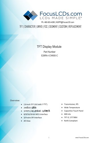
The document details the technical specifications for the 2.8-inch TFT Display Module, part number E28RA-I-CW600-C. It features a 240x320 pixel resolution, supports multiple interface types, and includes a capacitive touch panel. The module is suitable for wide temperature ranges and offers a brightness of 600 nits.
- Display Area: 43.20(H) x 57.60(V) mm
- Display Colors: 65k/262k
- Operating Temperature: -20 to +70°C
- Storage Temperature: -30 to +80°C
- Controller IC: ST7789V
- Module Size: 50.50 x 69.70 x 4.36 mm
- Weight: 30 g
- Contrast Ratio: 600-800%
- Response Time: 30-40 ms
- Viewing Angle: 80 degrees in all directions
- Supply Voltage: 2.5-3.6V
- Normal Mode Current: 8 mA
- Forward Current: 90-120 mA
- LED Lifetime: 50,000 hours
The module supports parallel RGB, 3-line SPI, and 4-line SPI interfaces. Timing diagrams and tables are provided for synchronization and data transfer.
Reset timing requirements include pulse duration and cancel times for proper initialization and operation.
- Absolute Maximum Rating: VDD ranges from 2.7 to 3.6 V, and VDDIO ranges from 1.8 to 3.6 V. Operating and storage temperatures are between -30 to +85℃.
- DC Electrical Characteristics: At 25℃, VDD ranges from 2.7 to 3.47 V, and VDDIO ranges from 1.8 to 3.6 V. Normal operation current is 11 mA, and sleep mode is 42 uA.
- AC Characteristics: OSC clock frequency is 49 to 51 MHz, and sensor clock ranges from 50 to 400 kHz.
The I2C interface operates in slave mode with a maximum SCL frequency of 400 kHz. Timing includes a bus free time of 1.3 us and a data setup time of 100 us.
Key parameters include a rise time from 0.1VDD to 0.9VDD of up to 5 ms and a reset time of at least 1 ms.
- Modules should be assembled without warping, protected from shock, and kept clean. Avoid chemicals like acetone and toluene on the polarizer.
- Static protection is crucial, and modules should not be disassembled or connected/disconnected while powered on.
- Store modules at 0 to 35℃ with less than 70% humidity, away from sunlight and UV exposure. Avoid condensation to prevent failures.
Catalog excerpts

TFT | CHARACTER | UWVD | FSC | SEGMENT | CUSTOM | REPLACEMENT TFT Display Module Part Number E28RA-I-CW600-C • Wide Temperature • Capacitive Touch Panel
Open the catalog to page 1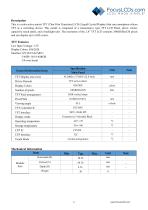
This is a color active matrix TFT (Thin Film Transistor) LCD (Liquid Crystal Display) that uses amorphous silicon TFT as a switching device. This model is composed of a transmissive type TFT LCD Panel, driver circuit, capacitive touch panel, and a backlight unit. The resolution of the 2.8” TFT LCD contains 240(RGB)x320 pixels and can display up to 262k colors. Low Input Voltage: 3.3 V Display Colors: 65k/262k Interface: 8/9/16/18-bit MCU 3/4SPI+ 16/18-bitRGB 3/4-wire Serial
Open the catalog to page 2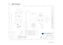
NOTE: MCU interface SET for IM PINS. 1. DISPLAY TYPE: 2.8”, TFT-LCD, 65K/262K COLORS 2. DISPLAY MODE: NORMALLY BLACK/IPS 3/4SPI+16/18Bit RGB Interface 3—line/4—line Serial Interface 6. Touch Mode: CTP Touch Driver 1C: ET5436 Touch Interface: IIC Touch mode: Five points Touch and LCM Bonding technology: Tape bonding CTP IIC Communication voltage: 3.3V 8. OPERATING TEMP: -20'C TO 70"C STORAGE TEMP: -30'C TO 80"C 9. BACK LIGHT: LED WHITE, 6 LED, 120mA, 3.2T0.3V 11. ” + "critical dimension/ Reference dimension. Interface type DBI Tyb_ 16-bit interface DBI Tyb_ 9-bit interface 3-Wire 9 BIT data serial...
Open the catalog to page 3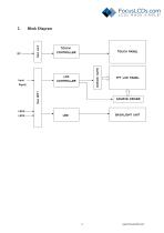
Block Diagram
Open the catalog to page 4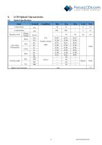
4. LCD Optical Characteristics 4.1 Optical Specifications
Open the catalog to page 6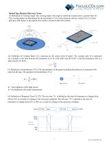
Optical Specification Reference Notes: (1) Definition of Viewing Angle: The viewing angle is the angle at which the contrast ratio is greater than 10. The viewing angles are determined for the horizontal or 3,9 o'clock direction and the vertical or 6,12 o'clock direction with respect to the optical axis which is normal to the LCD surface. (2) Definition of Contrast Ratio (Cr): measured at the center point of panel. The contrast ratio (Cr) measured on a module, is the ratio between the luminance (Lw) in a full white area (R=G=B=1) and the luminance (Ld) in a dark area (R=G=B=0). Lw Cr = Ld (3)...
Open the catalog to page 7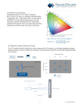
(5) Definition of Color Gamut: Measuring machine CFT-01. NTSC’s Primaries: R(x,y,Y),G(x,y,Y), B(x,y,Y). FPM520 of Westar Display Technologies, INC., which utilized SR-3 for Chromaticity and BM-5A for other optical characteristics.The color chromaticity shall be calculated from the spectral data measured with all pixels first in red, green, blue and white. Measurements shall be made at the center of the panel. (6) Definition of Optical Measurement Setup: The LCD module should be stabilized at a given temperature for 20 minutes to avoid abrupt temperature change during measuring. In order to stabilize...
Open the catalog to page 8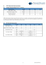
5. TFT Electrical Characteristics 5.1 Absolute Maximum Rating (Ta=25 °C, VSS=0V)
Open the catalog to page 9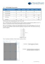
The back-light system is edge-lighting type with 6 white LEDs. Note 1: LED lifetime (Hr) can be defined as the time in which it continues to operate under the condition: Ta=25±3 °C, typical IL value indicated in the above table until the brightness becomes less than 50%. Note 2: The “LED lifetime” is defined as the module brightness decrease to 50% original brightness at Ta=25°C and IL=120mA. The LED lifetime could be decreased if operating IL is larger than 120mA. The constant current driving method is suggested. Note 3: Luminance Uniformity of these 9 points is defined as below: Luminance =...
Open the catalog to page 10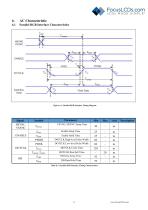
Parallel RGB Interface Characteristics Figure 6.1: Parallel RGB Interface Timing Diagram Signal HSYNC, VSYNC ENABLE Symbol ݑǰݑưݑ̰ݑpݐְݑ Parameter VSYNC, HSYNC Setup Time Enable Setup Time Enable Hold Time DOTCLK High-level Pulse Width DOTCLK Low-level Pulse Width DOTCLK Cycle Time װݑǰݑŰݐڰݐ۰ݑ , ŰݑǰݑŰݐڰݐ۰ݐ DOTCLK Rise/Fall Time DB Data Setup Time DB Data Hold Time
Open the catalog to page 11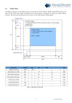
The display operation via the RGB interface is synchronized with the VSYNC, HSYNC and DOTCLK signals. The data can be written only within the specified area with low power consumption by using the window address function. The back porch andfront porch are used to set the RGB interface timing signals. Table 6.2: RGB Interface Timing Table
Open the catalog to page 12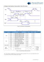
6.3 Display Serial Interface Characteristics (3-line SPI system) Figure 6.3: Serial Interface 3-SPI Timing Diagram Symbol TCSS TCSH TCSS TSCC TCHW TSCYCW TSHW TSLW TSCYCR TSHR TSLR TSDS TSDH TACC TOH Chip select setup time (write) Chip select hold time (write) Chip select setup time (read) Chip select hold time (read) Chip select ܢH” pulse width Serial clock cycle (write) SCL “H” pulse width (write) SCL “L” width (write) Serial clock cycle (read) SCL “H” pulse width (read) SCL “L” pulse width (read) Data setup time Data hold time Access time Output disable time Table 6.3: 3-line Serial Interface...
Open the catalog to page 13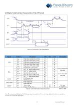
Table 6.5: 4-line Serial Interface Timing Characteristics min CL—8pF Note: The rising time and falling time (Tr, Tf) of input signal are specified at 15 ns or less. Logic high and low levels are specified as 30% and 70% of VDDI for Input signals.
Open the catalog to page 14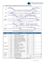
8080 Series MCU Parallel Interface Characteristics: 18/16/9/8-bit Bus Figure 6.5: Parallel Interface Timing Characteristics (8080-Series MCU Interface) TAHT TCHW Parameter Address setup time Address hold time (Write/Read) Chip select “H” pulse width TRDHFM TRDLFM Chip select setup time (Write) Chip select setup time (Read ID) Chip select setup time (Read FM) Chip select wait time (Write/Read) Chip select hold time Write cycle Control pulse “H” duration Control pulse “L” duration Read cycle (ID) Control pulse “H” duration (ID) Control pulse “L” duration Read cycle (FM) Control pulse “H” duration...
Open the catalog to page 15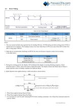
3. During the resetting period, the display will be blanked (the display is entering blanking sequence, which maximum time is 120ms, when reset starts in Sleep Out mode. The display remains the blank state in Sleep in mode) and then return to Default condition for Hardware Reset. 4. Spike Rejection also applies during a valid reset pulse as shown below: 5. When Reset applied during Sleep In Mode. 6. When Reset applied during Sleep Out Mode. 7. It is necessary to wait 5ms after releasing RESX before sending commands. Also Sleep Out command cannot be sent for 120ms.
Open the catalog to page 16All Focus LCDs catalogs and technical brochures
 KAB-M20SD-01
10 Pages
 E24RB-FW360-N
19 Pages
 C204A-BW-LW65
10 Pages
 E20RB-XW260-N
13 Pages
 G12864A1-FTW-LW63
13 Pages
 E17RG11216LW6M300-R
20 Pages
 C82A-BW-XW65
10 Pages
 C402A-FTW-LW63
10 Pages
 E43GB-I-MW405-C
17 Pages
 C204CXBSGSW6WT33XAA
15 Pages
 G12864A-FTW-LW63
13 Pages
 E24RG12432LWIM800-C
20 Pages
 C402A-FTW-LW65
10 Pages
 G12864B-BW-DW63
12 Pages
 E43GB-I-MW800-CB
15 Pages
 E28RA-I-CW480-N
17 Pages
 C81A-BW-LW65
10 Pages
 C202C-YTY-LW63
10 Pages
 G255128A-FTW-DW63
7 Pages
- LCD display panel
- TFT display module
- Medical equipment display
- Outdoor display panel
- Control panel display panel
- Instrumentation display panel
- Compact display panel
- Digital signage display panel
- Portable display
- Sunlight-readable display panel
- 2" display
- Sensor display
- 3.5" display
- 2.4" display
- Transflective display
- Display with cover glass
- Battery-powered display