
- Catalogs
- Focus LCDs
- C204CXBSGSW6WT33XAA

C204CXBSGSW6WT33XAA
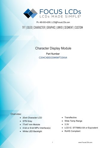
C204CXBSGSW6WT33XAA
The document outlines the technical specifications for a 20x4 Character LCD module, part number C204CXBSGSW6WT33XAA. Key features include a module size of 77x47 mm, STN Gray display type, white LED backlight, and an operating temperature range from -20°C to +70°C. It supports both 4-bit and 8-bit MPU interfaces and complies with RoHS standards.
- Character Display: 20x4
- Interface: 4-bit or 8-bit MPU
- LCD Type: STN Positive
- Viewing Angle: 6:00 O'Clock
- Backlight: White LED
- Operating Temperature: -20 to +70°C
- Storage Temperature: -30 to +80°C
- Module Size: 77.0 mm (H) x 47.0 mm (V) x 14.2 mm (D)
- Weight: 45 g
- VSS: Signal ground
- VDD: Power supply for logic (+3.3V)
- V0: Contrast adjust
- RS: Register select signal
- R/W: Read/write select signal
- E: Enable signal
- DB0-DB7: Data bus lines
- LED+: Power supply for backlight (+3.3V)
- LED-: Ground for backlight
- Input Voltage: 3.0 to 3.5 V
- Supply Current: 1.5 to 3.0 mA
- Backlight Supply Voltage: 3.3 V
- Backlight Supply Current: 10 uA
- Viewing Angle: 6 o'clock
- Contrast Ratio: 10
- Response Time: Rise 200-250 ms, Fall 300-350 ms
The module supports functions such as display clear, return home, entry mode set, display on/off control, cursor or display shift, and function set. It includes a busy flag for operation status and an address counter for DDRAM/CGRAM addressing.
The instruction set includes commands for display control, cursor movement, and data manipulation. Key instructions include clear display, return home, entry mode set, display on/off control, and cursor/display shift.
The document emphasizes not scaling off the drawing and refers to the Focus LCDs PDF drawing as the master file. It includes a disclaimer regarding proprietary and confidential information.
1. The RAM address is set by the previous address set instruction, which can be either DDRAM or CGRAM.
2. The address counter (AC) direction is determined by the RAM set instruction.
3. After a write operation, the address is automatically increased or decreased by 1, based on the entry mode.
4. For reading data from RAM, the selection is determined by the previous address set instruction. If not set, the first read data is invalid.
5. In DDRAM read operations, the cursor shift instruction acts like an address set instruction, transferring RAM data to the output register.
6. After read operations, the address counter is adjusted according to the entry mode.
7. CGRAM read operations may affect display shift execution.
General Precautions:
1. Handle LCD panels with care to avoid mechanical shock.
2. Clean the polarizer gently to avoid scratches.
3. Avoid tampering with metal frame tabs and unauthorized PCB modifications.
4. Ensure no stress is applied to the PCB during mounting.
5. Avoid pressing the metal bezel to prevent connector deformation.
6. Handle liquid crystal leaks with care, washing off immediately if contact occurs.
Static Electricity Precautions:
1. Operators should be grounded when handling the module.
2. Avoid touching conductive parts and connection terminals with bare hands.
3. Store modules in anti-static containers.
4. Use grounded soldering irons and electric screwdrivers.
5. Maintain a relative humidity of 50-60% to prevent static.
Soldering Precautions:
1. Solder only on I/O terminals using grounded irons.
2. Maintain soldering temperature at 280°C±10°C for 3-4 seconds.
3. Use eutectic solder with resin flux and remove flux residue.
Operation Precautions:
1. Adjust viewing angle by varying LCD driving voltage.
2. Use symmetric pulse waveforms to avoid DC component damage.
3. Keep driving voltage within specified limits.
4. Response time increases with lower temperatures.
5. Avoid exceeding operational temperature ranges to prevent display issues.
6. Store under 40°C with humidity below 60% for long-term storage.
Catalog excerpts
TFT | OLED | CHARACTER | GRAPHIC | UWVD | SEGMENT | CUSTOM Character Display Module Part Number C204CXBSGSW6WT33XAA • Wide Temp Range • RoHS Compliant
Open the catalog to page 1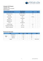
Characters: 20x4 Interface(s): 4-bit or 8-bit MPU RoHS Compliant
Open the catalog to page 2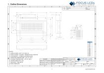
1. DISPLAY DRIVE: DUTY 1/16, VDD 3.3V 2. DISPLAY MODE: STN GRAY, TRANSFLECTIVE, POSITIVE 7. BACKLIGHT: SIDE WHITE Model Name:
Open the catalog to page 3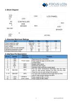
3. Absolute Maximum Ratings LCD PANEL \ / \
Open the catalog to page 4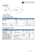
Contrast Adjust STN type display module (Ta=25°C, VDD=3.3V)
Open the catalog to page 5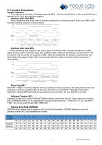
FOCUS LCDs LCDs MADE SIMPLE® 9. Function Description System Interface This chip has all two kinds of interface type with MPU : 4-bit bus and 8-bit bus. 4-bit bus and 8-bit bus is selected by DL bit in the instruction register. When interfacing data length is 8-bit, transfer is performed at a time through 8 ports, from DB0 to DB7. Example of timing sequence is shown below. Interface with 4-bit MPU When interfacing data length is 4-bit, only 4 ports, from DB4 to DB7, are used as data bus. At first higher 4-bit (in case of 8-bit bus mode, the contents of DB4 - DB7) are transferred, and then lower...
Open the catalog to page 7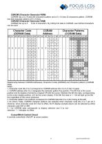
CGROM has a 5 x 8 dots 204 characters pattern and a 5 x 10 dots 32 characters pattern. CGROM has 204 character patterns of 5 x 8 dots. CGRAM (Character Generator RAM) CGRAM has up to 5 8 dot, 8 characters. By writing font data to CGRAM, user defined characters Relationship between CGRAM Addresses, Character Codes (DDRAM) and Character patterns (CGRAM Data) 1. Character code bits 0 to 2 correspond to CGRAM address bits 3 to 5 (3 bits: 8 types). 2. CGRAM address bits 0 to 2 designate the character pattern line position. The 8th line is the cursor position and its display is formed by a logical...
Open the catalog to page 8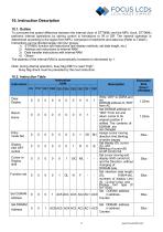
10. Instruction Description 10.1. Outline To overcome the speed difference between the internal clock of ST7066U and the MPU clock, ST7066U performs internal operations by storing control in formations to IR or DR. The internal operation is determined according to the signal from MPU, composed of read/write and data bus (Refer to Table7). Instructions can be divided largely into four groups: 1) ST7066U function set instructions (set display methods, set data length, etc.) 2) Address set instructions to internal RAM 3) Data transfer instructions with internal RAM The address of the internal RAM...
Open the catalog to page 9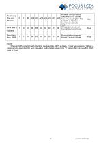
When an MPU program with checking the busy flag (DB7) is made, it must be necessary 1/2fosc is necessary for executing the next instruction by the falling edge of the “E” signal after the busy flag (DB7) goes to “Low”.
Open the catalog to page 10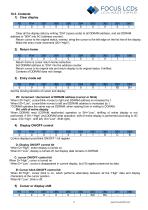
10.3. Contents 1) Clear display
Open the catalog to page 11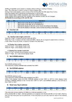
Shifting of right/left cursor position or display without writing or reading of display data. This instruction is used to correct or search display data. During 2-line mode display, cursor moves to the 2nd line after the 40th digit of the 1st line. Note that display shift is performed simultaneously in all the lines. When display data is shifted repeatedly, each line is shifted individually. When display shift is performed, the contents of the address counter are not changed. Shift patterns according to S/C and R/L bits This instruction shows whether ST7066U is in internal operation or not. If...
Open the catalog to page 12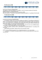
Read binary 8-bit data from DDRAM/CGRAM. The selection of RAM is set by the previous address set instruction. If the address set instruction of RAM is not performed before this instruction, the data that has been read first is invalid, as the direction of AC is not yet determined. If RAM data is read several times without RAM address instructions set before, read operation, the correct RAM data can be obtained from the second. But the first data would be incorrect, as there is no time margin to transfer RAM data. In case of DDRAM read operation, cursor shift instruction plays the same role as...
Open the catalog to page 13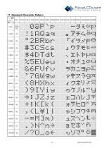
LCDs MADE SIMPLE®
Open the catalog to page 14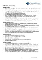
General Precautions: 1. LCD panel is made of glass. Avoid excessive mechanical shock or applying strong pressure onto the surface of display area. 2. The polarizer used on the display surface is easily scratched and damaged. Extreme care should be taken when handling. To clean dust or dirt off the display surface, wipe gently with cotton, or other soft material soaked with isoproply alcohol, ethyl alcohol or trichlorotriflorothan. Do not use water, ketone or aromatics and never scrub hard. 3. Do not tamper in any way with the tabs on the metal frame. 4. Do not make any modification on the PCB...
Open the catalog to page 15All Focus LCDs catalogs and technical brochures
 KAB-M20SD-01
10 Pages
 E28RA-I-CW600-C
20 Pages
 E24RB-FW360-N
19 Pages
 C204A-BW-LW65
10 Pages
 E20RB-XW260-N
13 Pages
 G12864A1-FTW-LW63
13 Pages
 E17RG11216LW6M300-R
20 Pages
 C82A-BW-XW65
10 Pages
 C402A-FTW-LW63
10 Pages
 E43GB-I-MW405-C
17 Pages
 G12864A-FTW-LW63
13 Pages
 E24RG12432LWIM800-C
20 Pages
 C402A-FTW-LW65
10 Pages
 G12864B-BW-DW63
12 Pages
 E43GB-I-MW800-CB
15 Pages
 E28RA-I-CW480-N
17 Pages
 C81A-BW-LW65
10 Pages
 C202C-YTY-LW63
10 Pages
 G255128A-FTW-DW63
7 Pages
- LCD display panel
- TFT display module
- Medical equipment display
- Outdoor display panel
- Control panel display panel
- Instrumentation display panel
- Compact display panel
- Digital signage display panel
- Portable display
- Sunlight-readable display panel
- 2" display
- Sensor display
- 3.5" display
- 2.4" display
- Transflective display
- Display with cover glass
- Battery-powered display