- Catalogs
- Fluke Calibration
- 6135A/PMUCAL
6135A/PMUCAL
1 /8Pages

6135A/PMUCAL
1 /8Pages
Catalog excerpts

6135A/PMUCAL Phasor Measurement Unit Calibration System Fast, automated, traceable calibrations that comply with IEEE C37.118.1a -2014 and IEEE Synchrophasor Measurement Test Suite Specification-Version 2-2015 TM
Open the catalog to page 1
The only commercially available, automated and traceable solution for PMU testing and calibration As the primary measurement and sensing tool in the Smart Grid, PMUs will play a broader role beyond avoiding blackouts. PMU data will be used to improve transmission and distribution efficiency by increasing the throughput and reducing line losses. Smart Grid A real-time, dynamic network of electrical demand, supply, and control GPS Satellite Provides accurate time stamp for grid activity. PMU relays Industrial plant Monitor and react to grid conditions in microseconds. Smart houses Meters and appliances...
Open the catalog to page 2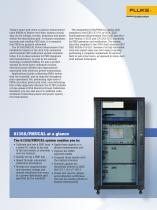
Today’s smart grid relies on phasor measurement units (PMUs) to deliver real-time, mission critical data on the voltage, current, frequency and phase within the distribution grid. To ensure consistent, accurate and credible PMU data, it is essential that PMUs be properly calibrated. The 6135A/PMUCAL Phasor Measurement Unit Calibration System is the only fully automated and traceable PMU calibration system available today. It is an ideal solution for PMU designers and manufacturers, as well as for national metrology institutes (NMIs). It’s also a perfect solution for third party calibration houses,...
Open the catalog to page 3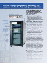
The only commercially available, automated and traceable solution for PMU testing and calibration Side input/output panel detail System software status panel System timing unit GPS receiver Server PC 6135A 3-Phase Electrical Power Standard System (6105A Electrical Power Standard) 6106A auxiliary unit 1 The 6135A/PMUCAL is made up of these hardware components, shipped in a 19-inch system rack with an integrated test connection panel: • Three-phase 6135A Electrical Power Standard: Includes one 6105A Electrical Power Standard Master Unit and two 6106A Electrical Power Standard Auxiliary Units. Provides...
Open the catalog to page 4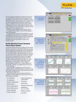
The test system architecture allows the client PC to access the test system over the Internet, from anywhere in the world. You can complete an automated PMU test in approximately six to eight hours per PMU configuration (frequency, sample rate, class), compared with many days using manual techniques. And the initial setup is also fast– just a few minutes of user interaction is required at the beginning of the automated test. System accuracy yields a test accuracy ratio of 10:1 against the the IEEE 37.118.1a-2014 measurement requirements. Creating reports with the 6135A/PMUCAL system is flexible...
Open the catalog to page 5
Client PC requirements • Microsoft® Windows 7 or later Operating System • Microsoft Excel 2003 or later • 2 GHz processor • 2 GB RAM • 20 GB free hard disk storage space for program and data • Network connection at > 300 KB/s • 32X DVD drive to install calibration software Electrical Source Accuracy Specifications See specifications in the 6100B/6105A Users Manual. Output voltage, per phase Output current, per phase Output current compliance Output frequency range Performance Specifications for C37.118.1a-2014 Tests Parameter Steady state Dynamic, modulation Dynamic, ramp Parameter Step time...
Open the catalog to page 6
PMU Test: Limits to Range of Influence Quantities General Test Limits Influence Quantity PMU nominal frequency PMU nominal magnitude Signal magnitude (percent of PMU nominal) Signal frequency range Test duration (single test) Range (voltage) 50 Hz or 60 Hz 10 V to 240 V 10 % to 120 % 44.0 Hz to 65.9 Hz 1 to 65,535 seconds Range (current) 50 Hz or 60 Hz 0 A to 10 A 10 % to 200 % 44.0 Hz to 65.9 Hz 1 to 65,535 seconds Steady State Tests Influence Quantity Phase angle Harmonic distortion - harmonic order1 Harmonic distortion - harmonic index 2 Out of band interference frequency Out of band interference...
Open the catalog to page 7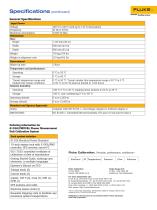
Specifications (continued) General Specifications Input Power Voltage Frequency Maximum consumption Dimensions Size: Height Weight in shipment crate Environment Warm-up time Temperature and performance: Operating Transit temperature range and limited time transit conditions Relative humidity: 0 °C to 50 °C. Transit outside this temperature range (-20 °C to 0 °C, or 50 °C to 60 °C) must be limited to <100 hours <80 % 5 °C to 30 °C ramping down linearly to 50 % at 35 °C Operating altitude Storage altitude Standard and Agency Approvals Safety Complies with IEC 61010-1, overvoltage category II, Pollution...
Open the catalog to page 8All Fluke Calibration catalogs and technical brochures
 9500C
9500C9 Pages
 P5514B Hydraulic
3 Pages
 Temperature Calibration
40 Pages
 Field Metrology Wells
6 Pages
 molbox1+™ Flow Terminal
6 Pages
 Fluke Precison Measurement
24 Pages
 Triple Point of Water Cells
4 Pages
 Micro-Baths
2 Pages
 Really Cold Baths
2 Pages
 The “DewK” Thermo-Hygrometer
4 Pages


- Temperature probe
- Measuring device
- Resistance temperature sensor
- Pressure gauge
- FLUKE calibrator
- Digital temperature control
- FLUKE digital thermometer
- Industrial thermometer
- Temperature controller
- Thermocouple temperature transducer
- °C thermometer
- Stainless steel temperature transducer
- Digital gauge
- Digital temperature controller
- Multimeter
- FLUKE portable calibrator
- Portable pyrometer
- Digital multimeter
- Stainless steel thermometer
- FLUKE temperature calibrator