- Catalogs
- Fluitronics GmbH
- MEV - Electrical operation
MEV - Electrical operation

MEV - Electrical operation
- Load-independent flow control with spool position proportional to electrical input.
- Pump pressure matches user pressure with compensators available in 3, 6, 8, or 12 bar.
- Built-in pump-unloading valve minimizes power loss and reduces load on the prime mover.
- User speed is precisely controlled under all load conditions.
- Progressive regulating curve ensures no pressure peaks and sensitive control.
- Constant working speed of differential cylinders with varying flow to the valve.
- Constant recirculation pressure regardless of the number of units.
- Flow limiting for each user port.
- Load-independent switching adjustment with constant acceleration and deceleration.
- Proportional solenoids with extended life, explosion-proof options available.
- Available in manual and hydraulic proportional series.
- Sub-plate system allows construction of up to 8 control valves.
- Operating pressure: 350 bar (5000 psi).
- Maximum return pressure: 15 bar (aluminium), 30 bar (cast iron).
- Pressure setting range: 5 to 350 bar.
- Flow range: up to 800 l/min.
- Fluid: Mineral oil, temperature range -35 to +80°C.
- Viscosity range: 2.8 to 380 cSt.
- Nominal voltage: 12V, 24V.
- Protection: IP 65, optional IP67.
AMCA proportional directional control valves offer pressure-compensated control of force, speed, acceleration, and deceleration, independent of load, overcoming challenges faced by conventional directional control valves.
- By-pass (3-way) flow control valve (MUV) for energy saving and load-independent flow control.
- Series (2-way) flow control valve (MDM) for energy saving and load-independent flow control.
- Proportional directional control valve with electrically controlled pilot stage for precise control.
The AMCA system consists of pressure relief or reducing valves, a 4/3 directional control valve, and ganged sub-plates.
- Port connections for low back pressure and large return flow management.
- T2: Main port to tank.
- T3: External pilot drain, necessary if backpressure exceeds 6 bar.
- X: Auxiliary port for remote pressure control or unloading the system.
- X2: External pilot supply for low load conditions.
- Y and Z: Auxiliary ports for pressure adjustments and load sensing.
- Compensator Variants: Adjustable recirculation pressure between 6-12 bar.
- Pressure Adjustments: Options for manual or electrical remote control.
- Spool Types: Various spool types are available for different flow requirements.
- Electrical Control: Options for proportional or on/off control.
- Solenoid Types: Different solenoid configurations for various voltage and environmental conditions.
- Concrete pump in Australia.
- Swing bridge in Britain.
- Fire ladder in France.
- Injection moulding machines in India and Italy.
- Nominal bore sizes and connecting threads.
- Weight and dimensions for various components.
- Instructions for customer-produced subplates.
Detailed specifications for subplates MEV, including dimensions in millimeters and inches, with precise measurements for each part.
- Mounting Procedure: Avoid overtightening mounting bolts to prevent mechanical distortion. Ensure mounting on a flat surface and use O-rings for sealing. Connect the B-port to the line with the largest return flow.
- Start-up Procedure: Begin with the relief valve adjustment screw fully released. Adjust clockwise to increase pressure, ensuring end-users are blocked during this process.
- Adjustment Procedure: The damping screw is factory-set but can be adjusted on-site. Valve response time is adjustable from 0.24 to 10 seconds.
- Flow Adjustment: Two methods are available: stroke limiter and ∆p adjustment, depending on configuration.
- Fluid Maintenance: Use mineral oil (ISO/VG-32) and maintain contamination levels at NAS 1638 class 9 or ISO 18/15.
- System Pressure Issues: Check for fouled relief valve cartridges, blocked damping throttles, or jammed spools.
- User Movement Issues: Address air in the system, faulty pilot valves, or excessive friction in components.
- Slow or No Movement: Investigate blocked damping throttles, low relief valve settings, or jammed spools.
- Pump Issues: Check for jammed spools or directional spool centering problems.
Various spare parts with their respective codes, including solenoids, springs, and seals, are listed with maximum tightening torques for different tierod sizes.
Detailed ordering codes are provided for various components like MUV, MDM, MEV, and AP, specifying series, size, mounting type, and options.
AMCA Hydraulic Fluid Power B.V. contact details are provided for further inquiries.
Catalog excerpts
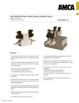
Publ. MEV...A-E-06/07 FEATURES * Load independent flow control corresponds to the spool-position proportional to the electrical input signal. * The pump pressure always corresponds to the user pressure, +3,6,8 or 12 bar (43, 86, 114 or 172 psi) Äp compensator. * The built-in pump-unloading valve results in: - very low power turned into heat; - minimum loading of the prime mover. * User speed is precisely controlled under all load conditions. * Progressive regulating curve; no pressure peaks when switching; sensitive control even for alternating pressures. * Constant working speed of differential cylinders at the different regulating flow to the valve by grinding angle. * Constant recirculation pressure independent of the number of units. * Any limiting of flow for every user port. * Load independent switching adjustment, constant acceleration and deceleration. * Proportional solenoids with longer life for the armature in the oil (explosion proof solenoids “II 2 EEx mII T4 or T5”, available). * Proportional directional control valves also available as: - Manual proportional series MHV and - Hydraulic proportional series MOV. Any combination of these control options is possible. * The sub plate system allows a construction up to 8 control valves. MEV PROPORTIONAL DIRECTIONAL CONTROL VALVE Electrical operation Sizes 12, 16, 20, 25, 32 Series MEV...A
Open the catalog to page 1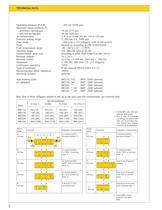
2 TECHNICAL DATA Operating pressure (P,A,B) ...350 bar (5000 psi) Maximum return pressure (T): - aluminium springcaps 15 bar (214 psi) - cast iron springcaps 30 bar (428 psi) Äp compensator 3; 6; 8 or 12 bar (43; 86; 114 or 172 psi) Pressure setting range 5...350 bar (72...5000 psi) Flow range ...800 l/min (...211 USgpm) - with 32 cSt at 40oC Fluid Mineral oil according to DIN 51524/51525 Fluid temperature range -35...+80°C (-31°...+176°F) Viscosity range 2,8...380 cSt, optimal 30 cSt Contamination level max. according to NAS 1638 Class 9 or ISO 18/15 Nominal voltage 12 V, 24 V Nominal current...
Open the catalog to page 2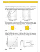
3 DESCRIPTION Conventional directional control valves control start, stop and directions of movement from hydraulic motors and cylinders. However, the speed of these users depends on the load pressure. If this load pressure varies, the speed is hardly controllable (figure 1) The AMCA proportional directional control valves are pressure compensated and achieve an ideal control of force, speed, acceleration and deceleration, independent of the load and increased demands (figure 2) The pressure compensator could be a pressure relief valve (MUV) or a pressure reducing valve (MDM), together with the...
Open the catalog to page 3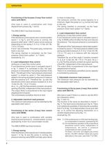
4 Functioning of the by-pass (3-way) flow control valve (with MUV) (this type is used in combination with fixed displacement pumps) (fig. 7 and 8) The AMCA-MUV has three functions: 1. Energy saving If the directional control spools are in neutral position (spool 1 in fig.7), and the pump is running, the pressure relief valve 1 (MUV) opens at low pressure (depending on the spring 3, 6, 8 or 12 bar (43, 86, 114 or 172 psi)). P and T are connected. The power (pxqv) turned into heat is very low. The spring chamber is connected, via the “loadpressure check back system”, to T (tank). (example fig....
Open the catalog to page 4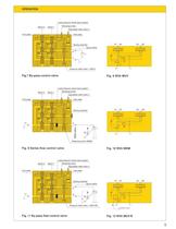
5 OPERATION another circuit Spool 2 B2 End plate A2 MDM orifice Pressure relief valve 1 (MUV) Pressure relief valve 1 (MUV/R) 0 Reducing valve (MDM) 0 M Inlet plate Spring chamber B1 T P A1 spool orifice T1 End plate Load-pressure check back system Adjustable relief valve 2 Spool 1 Damping-screw B2 B1 A2 A1 spool orifice R P M Spring chamber Inlet plate Damping-screw Load-pressure check back system Spool 2 Spool 1 Adjustable relief valve 2 Adjustable relief valve 2 Load-pressure check back system T1 B2 B1 End plate A2 A1 P Spring chamber Inlet plate Spool 2 Spool 1 Damping-screw P A1 B1 P T T...
Open the catalog to page 5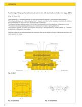
6 OPERATION Functioning of the proportional directional control valve with electrically controlled pilot stage. (MEV) (Fig. 13, 14 and 15) When solenoid a is actuated it pushes the pilot spool towards solenoid b and opens throttle position 1. This allows pilot pressure to the springchamber 1 (speed controlled by the adjustable restriction 5) and also through bore 3 to the end of the pilot spool opposite to solenoid a. The balance force on the pilot spool is the force of the solenoid which is proportional to the electric input. The balance force equates the pilot pressure in solenoid b and also...
Open the catalog to page 6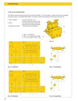
10 A..DM AP P MDM..A A A..EV T2 MEV..A b B a a A B P T b A..UV T P MUV..A A..EV A B AP A P MEV..A b a a T B b 3 1 2 CONFIGURATION TYPE OF VALVE MOUNTING The AMCA proportional directional control valves series MEV...A are sub-plate-, multiple sub-plate- and ganged sub-plate valves. A complete AMCA-MEV..A system consists for example of three main parts (fig 16) 1. MUV or MDM : pressure relief (fig 17) or pressure reducing valve (fig 18)). 2. MEV : 4/3 directional control valve with electrically controlled pilot stage. 3. Ganged sub-plates : including inlet- and endplate Fig. 17 (detailed) Fig....
Open the catalog to page 10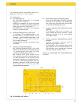
11 OPTIONS The following options are possible (see fig 19, application (example) and ordering code). Port connections: T2 : Low back pressure. - if a MUV-valve is mounted, T2 is normally plugged in the subplate, or - if there are cylinders in the circuit with a large returnflow, T2 shall be connected to tank for a lower return pressure in the valve, or - if a MDM-valve is mounted on the subplate, T2 is the mainport to tank. T3 : External pilot drain (on the pilot stage). - is neccesary if the backpressure in the returnline rises continually above 6 bar, for example a spring loaded check valve...
Open the catalog to page 11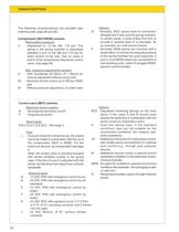
12 VARIANTS/OPTIONS The following variants/options are possible (see ordering code, page 26 and 28). Compensator (MUV/MDM) variants: Recirculation pressure: V : Adjustment 6...12 bar (86...172 psi). The spring in the spring chamber is adjustable between 6 and 12 bar (86 and 172 psi) for exact control of the max. flow on users A and B of the proportional directional control valve. (see page 26) Max. pressure adjustments variants: H : With handwheel (Ø 30mm, Ø 1.18inch) for manual adjustment without using tools E2 : Electrical remote control up to 350 bar (5000 psi) W : Without pressure adjustment,...
Open the catalog to page 12All Fluitronics GmbH catalogs and technical brochures
 CC-KL - Filtercart
2 Pages
 Radio remote control system
3 Pages
 HK - Tipping valve
2 Pages
 MDM-5 - Electrical operation
4 Pages
 MOV - Hydraulic operation
2 Pages
 MHV - Manual operation
28 Pages


- Hydraulic directional control valve
- Pack unit
- Spool hydraulic directional control valve
- Electric hydraulic power unit
- Electrically-operated hydraulic directional control valve
- Manual hydraulic directional control valve
- Compact hydraulic power unit
- Mobile hydraulic power unit
- Compact hydraulic directional control valve
- 4-way hydraulic directional control valve
- Lever-operated hydraulic directional control valve
- Proportional hydraulic directional control valve
- Stationary hydraulic power unit
- Electro-hydraulic hydraulic directional control valve
- 3-way hydraulic directional control valve
- Pilot-operated hydraulic directional control valve
- Solenoid-operated hydraulic directional control valve
- 3/2-way hydraulic directional control valve
- Lifting hydraulic power unit