- Catalogs
- Fluitronics GmbH
- F12K/F18K - Electrical, Manual and Hydraulic operation
F12K/F18K - Electrical, Manual and Hydraulic operation

F12K/F18K - Electrical, Manual and Hydraulic operation
Key Features:
- Compatible with all pump systems using a combiplate for different flow combinations.
- Output flow is load-independent and proportional to the input signal.
- Maximum operating pressure is 350 bar (5000 psi), with customizable pressure settings at ports A & B.
- Available in various main spool types and nominal flows, with flow customization through spool size adjustments or stroke limitations.
- Conforms to ISO standards for pressure differential flow characteristics, performance, valve port identification, and graphic symbols.
- Control options include electrical, manual, and hydraulic, with energy-saving load-sensing options and explosion-proof control solenoids.
Technical Data:
- Optional mounting position, with working port sizes of 1/2" BSP and 1" BSP.
- Operating pressure for ports P, A, B is 350 bar, with a maximum of 35 bar for port T.
- Pressure setting range is 13 to 350 bar, with a 7 bar pressure drop over the 2-way compensator.
- Max flow rates are 75 l/min for F12K and 200 l/min for F18K, with specified internal leakage rates.
- Fluid compatibility with mineral oil, temperature range of -30 to +80°C, and viscosity range of 10 to 500 cSt.
- Nominal voltage options are 12 V DC and 24 V DC, with specified nominal currents and reaction times.
Operation:
- The MFC valve enables simultaneous control of multiple loads from a single hydraulic pressure source, with each section fitted with a 2-way pressure compensator.
- Flow control is independent of supply pressure due to the compensator, reducing flow variation.
- Available with electrical, manual, and hydraulic controls, with optional adjustments and compensators.
- Load-sensing systems can be integrated, allowing separate adjustment of maximum flow rate and supply pressure for each service port.
Applications and Configurations:
- Examples include fixed and variable volume pump configurations, illustrating the use of inlet plates, pressure compensators, and load-sensing systems.
- Combiplate options are available for connecting different series, offering a cost-effective and flexible solution for compact valve combinations.
Diagrams and Performance Charts:
- Diagrams illustrate flow characteristics and pressure drop across different configurations and spool types.
- Performance charts demonstrate the relationship between pump pressure, load pressure, and flow rate, highlighting the valve's ability to maintain constant flow under varying conditions.
Catalog excerpts
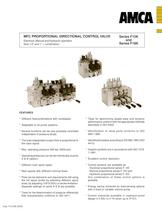
FEATURES * Different flowcombinations with combiplate. * Adaptable to all pump systems. * Several functions can be very precisely controlled independent of pressure drops. * The load independent output flow is proportional to the input signal. * Max. operating pressure 350 bar (5000 psi). * Operating pressures can be set individually at ports A & B (option). * Different main spool types. * Main spools with different nominal flows. * Flow can be tailored to suit requirements still using the full spool stroke by selecting different spool sizes, by adjusting (100 to 50%) or stroke limitation. Separate settings on ports A & B are possible. * Tests for the determination of pressure differential flow characteristics conforms to ISO 4411. MFC PROPORTIONAL DIRECTIONAL CONTROL VALVE Electrical, Manual and Hydraulic operation Size 1/2" and 1" + combination Series F12K and Series F18K * Tests for determining steady-state and dynamic performance conform with the appropriate methods described in ISO 6403. * Identification of valve ports conforms to ISO 9461:1992. * Identificationplates according to EN 982:1994 (ISO 4413). * Graphic symbols are in accordance with ISO 1219- 1:1991. * Excellent control resolution. * Control sections are available as: - Electrical proportional series F..KE - Manual proportional series F..KH and - Hydraulic proportional series F..KO Any combination of these control options is possible. * Energy saving achieved by load-sensing options with a fixed or variable volume pump. * Control solenoids available in explosion-proof design II 2 EEx m II T4 (even up to IP-57). Publ. F12/18K-03/06
Open the catalog to page 1
2 TECHNICAL DATA F12K F18K Mounting position Optional Optional Size working ports 1/2" BSP 1" BSP (SAE optional) (SAE optional) Operating pressure (P,A,B) ...350 bar (5000 psi) ...350 bar (5000 psi) Max. pressure (T) 35 bar (500 psi) 35 bar (500 psi) Pressure setting range 13...350 bar (186...5000 psi) 13...350 bar (186...5000 psi) Pressure drop over 2-way compensator (A,B) 7 bar (100 psi) 7 bar (100 psi) Internal pilot pressure setting approx.25 bar (358 psi) approx.25 bar (358 psi) Lever force 35N (7.8 lbs) 35N (7.8 lbs) Max. flow 75l/min (20 USgpm) 200l/min (53 USgpm) (see page 9) (see page...
Open the catalog to page 2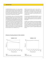
3 DESCRIPTION Influence of pump pressure to flow variation NOMINAL FLOW Flow qv % 0 50 100 150 200 250 300 350 bar (715) (1430) (2145) (2860) (3575) (4290) (5000) (psi) Pump pressure Fig. 1 With commercially available compensator 100 70 The AMCA Multi Flow Control - F..K - valve, enables the control of several loads simultaneously from only a single hydraulic pressure source. The MFC-valve was the first on the market to allow several loads to be controlled virtually independently due to the fact that each directional control section is fitted with a 2-way pressure compensator as standard. An...
Open the catalog to page 3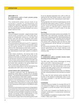
4 OPERATION AMCA-MFC-F..K in combination with a fixed volume pump (Example 1 on page 6). This combination allows several loads to be connected in parallel for simultaneously and independent operation regardless of the load/pump pressure variations while the flow through the valve can be proportionally controlled between zero and a preset maximum limit. Inlet Plate The circuit diagram (example 1, page 6) shows a fixed volume pump connected to an inlet plate with a pressure compensator acting as a by-pass flow control valve and also as a circulating valve when the directional spools of the control...
Open the catalog to page 4
5 ELECTRICAL F...KE Solenoids a = solenoid a energized; port A to pump 0 = solenoid a and b de-energized b = solenoid b energized; port B to pump. MANUAL F...KH Lever positions a = port A to pump o = neutral position b = port B to pump HYDRAULIC F...KO Pilot pressure ports a = pilot pressure port X under pressure; port A to pump 0 = pilot pressure ports X and Y without pressure b = pilot pressure port Y under pressure; port B to pump. OPERATION a 0 b a 0 b a 0 b A B a P T b X Y P T A B P A T B 0 b A a B A B pilot pressure port Y pilot pressure port X A B solenoid a solenoid b
Open the catalog to page 5
12 VARIANTS/OPTIONS SERIES F12K/F18K code R A B B code J A code E + F code A + B code H code J code E + F code A + B code H Variant D, E or F A B Variant W, X or Y Variant W, X or Y Variant D, E or F + FLOW LIMITATION SOLENOIDS PORT PRESSURE SETTING AND/OR PORT REMOTE CONTROL
Open the catalog to page 12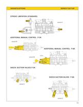
13 VARIANTS/OPTIONS SERIES F12K/F18K A B A B A B Airbleed A B Airbleed Airbleed A B STROKE LIMITATION (STANDARD) ADDITIONAL MANUAL CONTROL F12K SHOCK SUCTION VALVES F12K SHOCK SUCTION VALVES F18K variant H variant M variant M variant Z variant Z ADDITIONAL MANUAL CONTROL F18K
Open the catalog to page 13
14 APPLICATIONS SERIES F12K/F18K “HYDRALIFT” - PIPE HANDLING CRANE
Open the catalog to page 14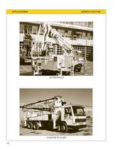
16 APPLICATIONS SERIES F12K/F18K SKYWORKER CONCRETE PUMP
Open the catalog to page 16
A2 B2 A3 B3 A4 B4 T1 F12KEWA1BH F12KERB1BHM F12KEWC1BH F12KPE4 A1 B1 A3 B3 A4 B4 F12KERA1BH T1 F12KPE4 F12KN F12KERB1BHM F12KEWC1BHZ A1 B1 A2 B2 F12KN F12KERA1BH M Ø F12KEWA1BHZ T2 P1 LS T2 LS P1 17 T1 F18KPH3 Y X A2 B2 Y X A3 B3 Y Va Vb Va F18KOWB1-HY F18KOWC1-FHY Vb T2 X A1 B1 LS Y T1 F18KU Va F18KPH2 P1 F18KORA1-FHZ R X A1 B1 Y X A2 B2 LS Vb Va Vb F18KR F18KOWB1-HY P1 F18KOWC1-FHY 1 A2 B2 T1 F12KHWC1FHZ F12KPH2 A1 B1 F12KHRA1FH T1 F12KN Z F12KPH4--Z A3 B3 A4 B4 F12KHWB1FH F12KHWC1FH T2 A1 B1 A2 B2 F12KHRA1FHZ LS P1 F12KU F12KHRA1FH P LS T2 APPLICATIONS SERIES F12K/F18K Parallel circuit with...
Open the catalog to page 17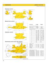
e solenoid a solenoid b A B 37 (1.44) 73 (2.85) 37 (1.44) 73 (2.85) Solenoid Code H (EEx m II T4) Solenoid Code J (IP 67 Military) (Explosion proof) 65 (2.54) 89 (3.47) 79 (3.1) 35 (1.37) 35 (1.37) 5,2 (0.20) 75 (2.93) 35 (1.37) 72 (2.81) (manual emergency control by button) Solenoid Codes E + F a c d b 68 (2.65) 18 effective stroke idle stroke effective stroke 31 (1.21) l b c 29 (1.13) f 78 (3.04) n r adjustment port A F12K adjustment port B F18K adjustment port B F12K adjustment port A F18K â manual lever auxiliary â P A m A B solenoid a pressure setting on A+B stroke limitation solenoid b...
Open the catalog to page 18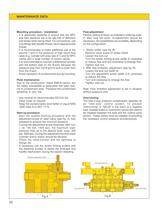
20 MAINTENANCE DATA Mounting procedure / Installation - It is absolutely essential to ensure that the MFC and their pipelines are to be laid free of distortion and stress when being fitted. For connections, use only fittings with parallel thread, never tapered screw thread. - It is recommended to make additional use of the second T port in the presence of high return-flow rates (e.g. cylinder with area ratio 2:1) and for MFC valves with a large number of control valves. - It is recommended to connect a differential cylinder with the bottom side on the B-port, because the pressure drop from the...
Open the catalog to page 20All Fluitronics GmbH catalogs and technical brochures
 CC-KL - Filtercart
2 Pages
 Radio remote control system
3 Pages
 HK - Tipping valve
2 Pages
 MDM-5 - Electrical operation
4 Pages
 MOV - Hydraulic operation
2 Pages
 MHV - Manual operation
28 Pages
 MEV - Electrical operation
32 Pages


- Hydraulic directional control valve
- SARRALLE hydraulic power unit
- Spool hydraulic directional control valve
- SARRALLE electrically-powered hydraulic power unit
- Electrically-operated hydraulic directional control valve
- Manual hydraulic directional control valve
- Compact hydraulic power unit
- Mobile hydraulic power unit
- Compact hydraulic directional control valve
- 4-way hydraulic directional control valve
- Lever-operated hydraulic directional control valve
- Proportional hydraulic directional control valve
- Stationary hydraulic power unit
- Electro-hydraulic hydraulic directional control valve
- 3-way hydraulic directional control valve
- Pilot-operated hydraulic directional control valve
- Solenoid-operated hydraulic directional control valve
- 3/2-way hydraulic directional control valve
- Lifting hydraulic power unit