ARIA
1 /29Pages

ARIA
1 /29Pages
Catalog excerpts
USER’S MANUAL
Open the catalog to page 1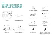
WHAT IS INCLUDED IN ARIA’S PACKAGE x4 USB Key (with Aria software) Power supply Fluidic outlet tubing (2m) Aria unit Tube cutter Inlet pressure tubing (2m)
Open the catalog to page 2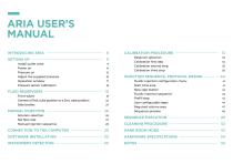
ARIA USER’S MANUAL INTRODUCING ARIA SETTING UP Install outlet valve Power on Pressure on Adjust the supplied pressure Operation window Pressure sensor calibration FLUID RESERVOIRS Front tubes Convert a 15mL tube position to a 2mL tube position Side bottles MANUAL INJECTION Solution selection Set flow rate Manual injection sequence CALIBRATION PROCEDURE Reservoir selection Calibration first step Calibration second step Calibration third step INJECTION SEQUENCE, PROTOCOL DESIGN Fluidic injection configuration menu Start time area New step button Fluidic injection sequence Prefill step User configurable...
Open the catalog to page 3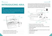
INTRODUCING ARIA INTRODUCING ARIA INTRODUCING ARIA Aria is a perfusion system which automates perfusion or timed injection protocols. It allows for the sequential delivery of of up 10 protocols. It allows for the sequential delivery up to to 10 different solutions at desired flow rate rate into a microfluidic different solutions at the the desired flow into a microfluidic chip, chip, perfusion chamber or petri perfusion chamber or petri dish. dish. Aria uses a pressure pumping principle to inject solutions. During injection, Aria pressurizes all the reservoirs and the selected solution is pushed...
Open the catalog to page 4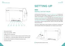
INTRODUCING ARIA SETTING UP INSTALL OUTLET VALVE In this section, the user will build up their fluidic circuit. In order to cut the tubing at the right length, Fluigent advises the user to place Aria where it will operate. It is recommended to place the external valve as close to the chip as possible. The tube cutter should be used to cut the fluidic outlet tubing at the right dimensions. It is recommended to minimize the fluidic pathway to optimize performance (reduce reagent consumption, injection responsiveness, maximum flow rate, estimated time of arrival, etc.). 7 Main power switch Aria...
Open the catalog to page 5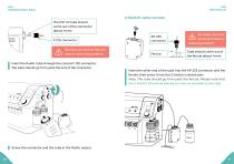
INTRODUCING ARIA 2-Switch valve version The 1/16’’ ID tube should come out of the connector (about 1mm) F-120 connector the tube cut must be flat and clean to avoid any problem. Insert the fluidic tube through the conical F-120 connector. The tube should go 1mm past the end of the connector. the tube cut must be flat and clean to avoid any problem. Tube should come out of the ferrule (about 1mm) Insert the other end of the tube into the XP-235 connector and the ferrule, then screw it into the 2-Switch’s central port. Note: The tube should go 1mm past the ferrule. Please note that the 2-Switch...
Open the catalog to page 6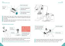
INTRODUCING ARIA Port 1 to the chip Port 2 to waste The light indicates the selected port The side button selects the outlet port Connect port 1 (port with 1 dot) to the chip and connect port 2 to the waste. The port lighted on the 2-Switch indicates the direction of the flow. To manually select the direction of the flow (to the waste or to the chip) press on the side button. M-Switch valve version the tube cut must be flat and clean to avoid any problem. Tube should come out of the ferrule (about 1mm) Insert the other end of the tube into the XP-235 connector and the ferrule, then screw it into...
Open the catalog to page 7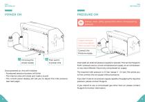
PRESSURE ON Always wear safety protection when manipulating pressure. Supply pressure recommandation: Never exceed 3 bar Connect the Pressure supply 1 First plug the power supply 2 Then switch to power Aria Once powered on, Aria will initialize: Numbered selection buttons will blink The internal valve will rotate and make a sound The control panel display will ask you to adjust the inlet pressure (see next page) Aria needs an external pressure supply to operate. This can be Fluigent’s FLPG+ pressure source, a local compressed air supply, an air compressor, or any clean (filtered <10μm) dry compressed...
Open the catalog to page 8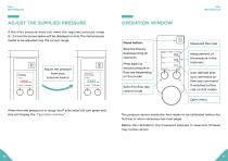
ADJUST THE SUPPLIED PRESSURE If the inlet pressure does not meet the required pressure range (2 – 2.4 bar) the screen below will be displayed on Aria. The inlet pressure needs to be adjusted into the correct range. OPERATION WINDOW Pause button: Stop the flow by depressurizing all reservoirs. Adjust the pressure from your pressure source Press again to recover pressure or flow rate (depending on the mode) Switch to flow rate control mode Measured flow rate Measurement of the pressure in the reservoirs User-defined pressure command (or flow rate command if switched to flow rate control mode) Open...
Open the catalog to page 9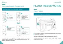
FLUID RESERVOIRS PRESSURE SENSOR CALIBRATION FLUID RESERVOIRS To be done before the first use or when necessary. Press “Menu” Use the dial (turn and press) to select “Pressure calibrate” An example of Pmeas before calibration Aria can remain powered on to proceed. Done! Pmeas value after calibration (Pmeas=0) Pull up the side handle to move the tube holder to the open position (the buttons will blink). The fluidic tubing is tilted to ease insertion into the reservoirs. Due to the high sensitivity of the internal pressure sensor, you may observe normal fluctuations of the measured pressure (Pmeas),...
Open the catalog to page 10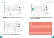
FLUID RESERVOIRS For 15mL tube: unscrew the tube, refill and screw it back in. FLUID RESERVOIRS Push down the handle to move the tube holder to the closed position (the buttons will stop blinking). Please note that a tube needs to be placed at each position even if the tube is empty and not used during the course of the experiment. If the tubes are not securely sealed the buttons above will blink. Please do not pull up the handle during an injection process. Doing this will cause Aria to depressurize all the reservoirs and stop the injection process. Please note that you should press the “Pause”...
Open the catalog to page 11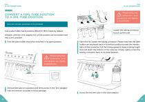
FLUID RESERVOIRS FLUID RESERVOIRS CONVERT A 15ML TUBE POSITION TO A 2ML TUBE POSITION Please verify that adaptors and connectors are tightly screwed back. Aria can remain powered on to proceed. Aria’s tube holder has 8 positions fitted for 15mL tubes by default. However, with the “2mL Adaptor Kit” a 15mL position can be transformed into a 2mL position. First the tube holder should be switched in its open position. Loosen the tubing connector to pull up the tube Open the lid, loosen the tubing connector. Please note that the tube holder can be placed back in its vertical position to ease the manipulation...
Open the catalog to page 12All FLUIGENT catalogs and technical brochures
 FLPG Plus
12 Pages
 PRODUCT CATALOG 2019
47 Pages


- Pump
- Pump with electric motor
- Manual valve
- Control valve
- Threaded valve
- Regulating valve
- HS automation software
- HS analysis software
- Electric valve
- HS real-time software
- Gas valve
- Microscope
- Standard valve
- Piston actuator valve
- Valve for the chemical industry
- HS monitoring software
- 2-channel valve
- HS interface software