
Catalog excerpts

Electromagnetic Flowmeter Electromagnetic Flowmeter Product Installation Guide and User Manual Flowtech Measuring Instruments Pvt Ltd Email: flowtech01@gmail.com/flowtechinstruments@yahoo.com Website: flowtech-instruments.com Mobile Number: 08469769988 / 9428876496 / 8160255957 CIN NO: U33129GJ2011PTC065518
Open the catalog to page 1
Electromagnetic Flowmeter
Open the catalog to page 2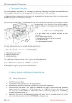
Electromagnetic Flowmeter 1. Operating Principle The electromagnetic flow meter is an instrument for measuring the flow of conductive fluid using Faraday's electromagnetic induction law, and consequently the fluid must be electrically conductive. As illustrated below a magnetic field with density B - perpendicular to the direction of flow - stretches across a fluid flowing within an electrically isolated pipe. The magnetic flux will induce a voltage difference (E) that can be measured between two electrodes arranged perpendicular to the direction of flow and the magnetic field. The voltage...
Open the catalog to page 3
The FLOWTECH flow converter/flow meter must not be mounted in explosion hazardous areas! Repair must only be made by FLOWTECH or by a service representative approved by FLOWTECH. 3. Flow Sensor The following conditions must be satisfied to get the full benefit of the MagFlux® flow sensor: 3.1 Minimum conductivity • The conductivity of the media must be greater than 5 pS/cm. 3.2 Liner selection • Use Teflon® lining for chemicals and food industries • Use hard rubber lining for drinking water and waste water • Use soft rubber lining for water with abrasive particles 3.3 Electrode selection •...
Open the catalog to page 4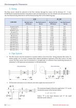
5. Sizing The flow sensor should be selected so the flow velocity through the sensor will be between 0.5 - 5 m/s. FLOWTECH recommends that flow velocities in tubes are kept between 3 m/s for reliable and safe operation. See also the dimensioning table below and the dimensioning chart on the following page. 6. Pipe System • The flow sensor must be mounted in a location which is free from inter- fering elements like valves, Ts, bends, pumps, etc. to ensure a laminar flow without turbulence upstream of the flow sensor. For that reason, the flow sensor must be mounted in a straight pipe at a...
Open the catalog to page 5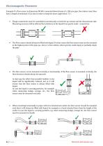
Electromagnetic Flowmeter Example: If a flow sensor in dimension DN 80 is mounted downstream of a 100 mm pipe, the reducer must then have a length of minimum 152,6 mm in order to keep the inner angle below 7,5 °. Flange connections must be assembled concentrically on both the up-stream and the downstream side. Measuring accuracy will be affected by turbulence in the liquid from poorly made connections The Flow sensor should always be filled with liquid. For that reason the flow sensor must not be mounted at the highest point of the pipe sys- tem or in free outlets, where gravity could empty...
Open the catalog to page 6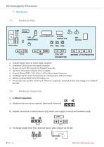
Electromagnetic Flowmeter • Connect Sensor wires to sensor input connector • Connector Coil wires to coil output connector • Proper connect LCD Connector & Keypad Connector • Any loose connection will give error in output • Connect Mains (230V / 110 AC) to L & N in Mains Input Connector • Earthing must be connected properly for safety purpose and best output • While providing MAINS LCD will display text • Do not alter any variable resistor pot. However, company's technical person may change to re-calibrate the unit a) Hardware has two source options. (Internal & External) b) Default...
Open the catalog to page 7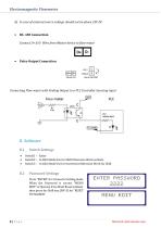
d) In case of external source voltage should not be above 25V DC • RS- 485 Connection Connect D+ & D- Wire from Master device to flow-meter • Pulse Output Connection PULSE O/P PULSE OUTPUT Connecting Flow-meter with Sinking Output to a PLC Controller Sourcing Input 8. Software 8.1 Switch Settings • Switchl - - Enter • Switch2 - - In Edit Mode Use for Shift Otherwise Work as Back. • Switch3 - - In Edit Mode Use for Increment Otherwise Work for Shift 8.2 Password Settings Press “ENTER” for 3 times for Setting mode When the Password is correct “MENU EDIT” is Opened, If we Want Reset totalizer...
Open the catalog to page 8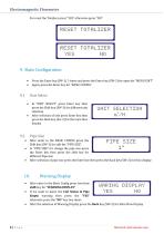
Electromagnetic Flowmeter For reset the Totalizer press” YES” otherwise press “NO” 9. Basic Configuration • Press the Enter key (SW-1) 3 times and press the Enter key (SW-3) for open the “MENU EDIT” • Again, press the Enter key for “BASIC CONFIG” 9.1 Unit Select • In “UNIT SELECT” press Enter key then press the Shift key (SW-3) for different unit selection • After selection of unit press Enter key then press the Back key (Sw-2) for the main flow display 9.2 Pipe Size • After enter in the BASIC CONFIG press the Shift key (SW-3) for edit the “PIPE SIZE” • In “PIPE SIZE” for change the pipe...
Open the catalog to page 9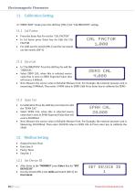
Electromagnetic Flowmeter In “MENU EDIT “mode press the shift key (SW-3) for “CALIBRATION” setting. 11.1 Cal Factor • Press the Enter Key For set the “CAL FACTOR” • In Cal factor press Enter key for Edit the CAL FACTOR • For shift use the switch (SW-2) and for increment use the switch (SW-3) 11.2 Zero Cal • In “CALIBRATION” Press the shift key for edit the “ZEROCAL” • Select ZERO CAL, when this is selected source value that is seen in ZERO Expected Value that will source 4.000mA. • Now Measure the source value in Reliable Measure Unit. For Example, the external measure unit is measuring...
Open the catalog to page 10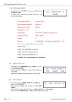
Electromagnetic Flowmeter 12.2 SET BAUD RATE • After Enter in the “MODBUS” Setting press Shift Key for “SET BAUD RATE” • In BAUD RATE, Use Increment key (SW-3) For set Different Baud Rate Transmission mode Slave response time out Delay between polls Default Device ID Default Data Starting Address Length Register : Standard RTU :2000 ms : 250 ms : 1 : Float: Most significant register first : 0001 (30001) : 6 : Input Register (Modbus Function Code FC = 4). Data Format as Float (Not Swapped Float) Address Map: 30001: Flow (Unit will be Ltr/Hour) 30003: Totalizer1 (Unit will be Ltr) 30005:...
Open the catalog to page 11All Flowtech Measuring Instruments Pvt. Ltd. catalogs and technical brochures
-
DIESEL FLOW METER
5 Pages
-
FRP GRATINGS
4 Pages
-
TUBULAR LEVEL INDICATOR
5 Pages
-
TOP MOUNTED LEVEL SWITCH
2 Pages
-
TOP MOUNTED LEVEL INDICATOR
6 Pages
-
SIDE MOUNTED LEVEL SWITCH
2 Pages
-
LEVEL TRANSMITTER
3 Pages
-
SIGHT GLASS INDICATOR
3 Pages
-
REFLEX LEVEL GAUGE
6 Pages
-
FUEL FLOW METER
5 Pages
-
MAGNETIC LEVEL INDICATOR
6 Pages
-
OIL FLOW METER
3 Pages
-
ORIFICE FLANGE ASSEMBLY
6 Pages
-
GLASS TUBE ROTAMETER
6 Pages
-
PLASTIC HELICAL FLOW METER
3 Pages
-
BYPASS ROTAMETER
5 Pages
-
ACRYLIC BODY ROTAMETER
4 Pages
-
Helical Flow Meter
7 Pages
Archived catalogs
-
TURBINE FLOW METER
7 Pages


