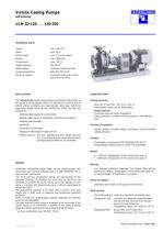
Group: Flowserve

Catalog excerpts
TECHNICAL DATA Suction head: Casing pressure: Shaft sealing: Flange connections: standard mechanical seal clockwise when seen on the pump from the drive The self-priming volute casing pumps according to DIN 24255 of the series ULN are applied when it is necessary to suck in and to handle without problems and automatically, pure resp. turbid not aggressive liquids which do not contain any solids. So they are drinking water supply for communities general water supply in agriculture, business and industry charge and discharge of fuels and oils Please observe: the max. geodetical suction height amounts to 5 m, provided that the necessary pressure corresponding to NPSH is not exceeded. Casing pressure: Intermediate values can be interpolated. Please observe: Technical rules and safety regulations. Casing pressure = positive suction pressure + zero delivery Suction branch directed axially, discharge branch directed radially upwards. Flange design drilled accord, to ANSI 150 is possible. Horizontal, self-priming single stage volume casing pumps with dimensions and nominal outputs accord, to DIN 24255/EN 733 in back pull out construction. The back pull out construction allows the demounting of the complete bearing unit towards the drive side so that it is not necessary to detach the pump casing out of the pipings. On ap- plying a coupling with dismounting piece it will be superfluous to The programme consists of 27 sizes with 4 suction sizes and needs only 2 shaft units on applying the mechanical assembly Within a shaft unit, shaft sealing, impeller fastening and bearing The side channel suction stage is arranged at the drive side of the volute casing. It is connected in parallel to the liquid pumping stage and works according to the sucking through principle. 1) up from construction size 100-200 10 bar n = 1450 rpm; Designation of this construction type: A- n = 2900 rpm; Designation of this construction type: B- Two greased antifriction bearings. First grease filling will be made in the factory.. Designation of this construction type: B As special design oil lubrification is possible. Clockwise when seen on the pump from the drive. Shaft sealing: The shaft sealing is made by a standard mechanical seal. Designation AAE: uncooled, not balanced single standard mechanical seal, flushed from internal source, O-rings Perbunan. Designation AA1 : as per AAE, but O-rings Viton.
Open the catalog to page 1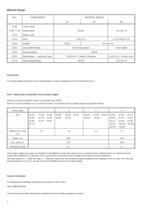
Material design Casing seal: For casing sealing a flat type seal of special paper is used. Designation of this construction type: 2 Drive / Speed and co-ordination of the suction stages: Drive by commercial electric motors, construction type IM B3. Drive by V-belt is admitted up to 1,5 kW drive power. On request, drive by Diesel engines or gasoline motors. The suction stages have been co-ordinated to the different construction sizes in such a manner that an optimal time at an economical drive power will be attained. On selecting of the motor size for the pump unit this constant drive power...
Open the catalog to page 2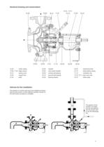
Sectional drawing and nomenclature 23.50 vane wheel impeller 32.00 inclined ball bearing 32.10 grooved ball bearing 47.10 shaft sealing casing 73.10,73.11 pipe union with The pipeline on suction side has to be installed as shown, above pump centre, so that sufficient quantity of liquid for the self suction procedure is available.
Open the catalog to page 3
Performance graph
Open the catalog to page 4
Characteristic curves n = 2900 rpm Attention: On selecting the motors, the constant drive power of the pertinent suction stage has to be added to the drive values determined out of the characteristic curves motor power = P + 0,3 kW motor power = P + 0,3 kW motor power = P + 0,3 kW motor power = P + 0,3 kW 5
Open the catalog to page 5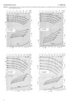
Characteristic curves n = 2900 rpm Attention: On selecting the motors, the constant drive power of the pertinent suction stage has to be added to the drive values determined out of the characteristic curves motor power = P + 0,3 kW motor power = P + 0,3 kW 6 motor power = P + 0,3 kW motor power = P + 0,3 kW
Open the catalog to page 6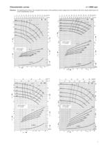
Characteristic curves Attention: On selecting the motors, the constant drive power of the pertinent suction stage has to be added to the drive values determined out
Open the catalog to page 7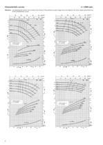
Characteristic curves n = 2900 rpm Attention: On selecting the motors, the constant drive power of the pertinent suction stage has to be added to the drive values determined out of the characteristic curves motor power = P + 0,3 kW motor power = P + 0,9 kW 8 motor power = P + 0,9 kW motor power = P + 2,2 kW
Open the catalog to page 8
Characteristic curves Attention: On selecting the motors, the constant drive power of the pertinent suction stage has to be added to the drive values determined out
Open the catalog to page 9
Characteristic curves n = 2900 rpm Attention: On selecting the motors, the constant drive power of the pertinent suction stage has to be added to the drive values determined out of the characteristic curves max. motor power motor power = P + 2,2 kW n = 1450 rpm motor power = P + 0,7 kW 10 motor power = P + 0,7 kW
Open the catalog to page 10
Characteristic curves n = 1450 rpm Attention: On selecting the motors, the constant drive power of the pertinent suction stage has to be added to the drive values determined out of the characteristic curves motor power = P + 0,7 kW motor power = P + 0,7 kW motor power = P + 0,7 kW motor power = P + 0,7 kW 11
Open the catalog to page 11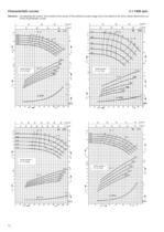
Characteristic curves n = 1450 rpm Attention: On selecting the motors, the constant drive power of the pertinent suction stage has to be added to the drive values determined out of the characteristic curves motor power = P + 0,7 kW motor power = P + 0,7 kW motor power = P + 0,7 kW motor power = P + 0,7 kW 12
Open the catalog to page 12
Characteristic curves n = 1450 rpm Attention: On selecting the motors, the constant drive power of the pertinent suction stage has to be added to the drive values determined out of the characteristic curves motor power = P + 0,7 kW motor power = P + 0,7 kW motor power = P + 0,7 kW motor power = P + 0,7 kW 13
Open the catalog to page 13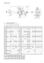
Dimension table In = connection for air ventilation pipe G 3/8 UAL = connection for leak liquid G % Ue = connection for discharge G % from DNA 65 G 3/8 1) Pipe bend can be delivered as accessory by the factory.
Open the catalog to page 15All Flowserve SIHI Pumps catalogs and technical brochures
-
 Type NHK and SHK
24 Pages
-
 SIHIsanivac 400, 800, 1000
4 Pages
-
 PL 325 M
14 Pages
-
 PL 91 M, PL 126 M, PL 161 M
16 Pages
-
 SIHI ® Gas separation
8 Pages
-
 SIHI Liquid Ring Compressors
8 Pages
-
 Side Channel Pumps
12 Pages
-
 LPG Solutions
12 Pages
-
 SIHISuperNova ZHND 032160
14 Pages
-
 SIHImodular PL 251 M
13 Pages
-
 LEM 26, LEM 51
7 Pages
-
 LEM 325, LEM 425
8 Pages
-
 Applications and Products
9 Pages
-
 Series MFS, 7,200 m³/h
2 Pages
-
 Sludge Mixer MFS
2 Pages
-
 Mixed Flow, Volute Casing Pump
11 Pages
-
 Volute casing pumps
26 Pages
-
 Non-clogging Pump
19 Pages
-
 Volute casing pump CBT
11 Pages


