User Guide

User Guide
History and Introduction: The Flowdrill system, developed to create holes in thin steel sheets using frictional heat, faced initial challenges in 1923 due to unavailable materials and technology. It is ideal for automation, offering benefits like no swarf, long tool life, and accurate hole formation, and is widely used in industries such as automotive and household appliances.
How Flowdrill Works: The tool consists of a pointed end, cone, and parallel body. High axial pressure and rotational speed generate heat, allowing the tool to penetrate and form a bushing from displaced material.
Flowdrill Parameters: Key parameters include axial force, speed, power, and material thickness. The diameter of the Flowdrill determines these values, and adjustments are necessary based on material type and thickness.
Flowdrill Types and Applications: There are long and short Flowdrills, each designed for specific applications. They are primarily used for creating high-strength threaded connections in thin materials and can also be used for soldered connections and bearing supports.
Suitable Materials: Flowdrills are effective on steel, non-ferrous metals, aluminum, and stainless steel, with some exceptions for brittle materials.
Working Life Influential Factors: Factors affecting tool life include thermal stress, mechanical shock, radial forces, and lubrication. Regular maintenance and proper handling can extend the tool's lifespan.
Work-piece Material and Lubrication: Lubrication is crucial to prevent adhesion and ensure smooth operation, especially in aluminum. Specific lubricants are recommended for different materials.
Tapping Information: Tapping torque depends on various factors, and cold forming threads require more torque than cutting. Recommended Flowdrill diameters ensure optimal thread depth.
Specifications: The document outlines the advantages of using cold forming processes over cutting taps, highlighting increased thread strength. It specifies the use of larger Flowdrill diameters for improved tool life and performance in tough materials. Key parameters such as RPM, roughbore diameter, pitch, and lubrication are discussed in relation to their impact on torque and tool performance.
Procedures: The document details the Flowdrill process, emphasizing the importance of initial pressure to create frictional heating, which softens the material and allows the drill to advance. It provides guidelines for feed rates, which vary based on Flowdrill size, speed, material type, and thickness. The document includes CNC programming examples for drilling through mild steel, specifying feed rates at different stages of the process.
Tools and Accessories: A list of tools and accessories is provided, including Flowdrill sizes, lubricants, toolholders, collets, and optional extras like tapping attachments and diamond files. The document also mentions the average life expectancy of tools, such as the Flowtap M8, which can create approximately 10,000 holes.
Tables and Data: Extensive tables provide data on torque, pull-out strength, and maximum material thickness for various thread sizes. The tables also include motor capacity, RPM, and production time for different Flowdrill diameters and thread sizes. This data is crucial for selecting the right tools and settings for specific applications.
Recommendations and Best Practices: The document offers tips for optimizing the Flowdrill process, such as maintaining a constant dull red glow during drilling and adjusting feed rates to prevent tool overheating. It advises on lubrication and checking tool speed and pressure settings to ensure efficient operation.
Conclusion: This technical guide serves as a valuable resource for professionals using Flowdrill and Flowtap tools, providing detailed instructions and data to enhance the efficiency and quality of thread creation in various materials.
Catalog excerpts

All rights reserved. No part of this publication may be reproduced or transmitted in any form or by any means, electronic or mechanical, including photocopy, recording or any information storage and retrieval system, without permission in writing from the publisher.This handbook has been carefully prepared and translated.Flowdrill does not accept any responsibility for errors in the handbook and any consequences resultant therefrom. No guarantee can be given that the details are free from patent rights assigned to third parties. All data and comparative details should be understood as being indicative...
Open the catalog to page 2
The Flowdrill > System > 3 Toolholder with Nut, Spanner and "C" Spanner-FDMC2 -FDMC3Collets-Fd 430e 6 up till 14 -Fd 470e 12 up till 20 -Rubber flex colletsFlowdrills and Flowtaps -Standard (see cover at the back) -SpecialsLubricants and Miscellaneous size="-3">
Open the catalog to page 5
(a)No swarf(b)Long tool life (c)Accurate hole formMuch experience has been gained in theautomobile, gas-heating, metal furniture, lighting and household appliance indus-tries, etc.Although the process itself has beenapplied for some time, it is necessary for the user to understand the nature of the Flowdrill process, the various types of Flowdrills and the physical requirements of the drilling machine for best results. for any column drilling machineAutomatic Turret drilling Head suitable >
Open the catalog to page 8
The standard Flowdrill design is shown in figure 3. Its working portion consists of a pointed end, a cone and a parallel body. Both the cone and the body are polygon shaped. This specially designed shape plays an essential part in the Flowdrill process. The Flowdrill also has a collar and a straight shank. Flowdrills are made of a carbide grade developed to satisfy the unique charac- teristics of the Flowdrill operation. > -Develops heat rapidly in Flowdrill creating thermal stress.-Increases feed rate - reduces drillingtime.-May alter the physical properties ofworkpiece material. Relatively...
Open the catalog to page 9
Material thickness (h)Flowdrill dia. Speed (n) Drilling time1. 5 sec. 2.0 sec. FlowdrillTemperature 2.0 mm1750 min-12.0 mm3 000 min- 1 700 C600 ں C7.3mm 7.3mm >
Open the catalog to page 14
Maximum material thickness (h.Max) isproportional to the Flowdrill diameter. Minimum thickness follows the general rule: h Min = approx. 0.2 x D 1 up to 2mm, which rule is suitable for most of the bigger sizes. D1 is the Flowdrill diameter.Flowdrill life is reduced if used on heavier gauge material or materials with high tensile strength.Notes: Fig. 6 indicates maximum materialthickness that can be Flowdrilled with standard long or short Flowdrills. See also table in chapter 16.0 Special Flowdrills can be supplied to meet unusual needs. For greater thickness an extra long L 5 may be necessary....
Open the catalog to page 16
The long Flowdrill has a long parallel body (L5)(fig.7) designed to produce a hole that is cylindrical for the entire bush length. Material that is backward extruded is rolled into a rim by the Flowdrill collar (fig. 8e). > Short Flowdrills have a shorter parallel body. This design produces a bush that is conical and provides great strength when formed into a thread (fig. 8a). > Special L 4 & L 5 dimensions are avai- lable for use when Flowdrill penetration length is restricted for example in small diameter tube. fig. 7 fig. 7b fig. 7c fig. 7a >
Open the catalog to page 18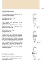
The following optional features can be supplied on any Flowdrill: > The Flowdrill collar is ground into a cutter (fig. 8c,g). This removes the rim formed around the top surface of a Flowdrilled hole, leaving the surface flat. fig . 7d fig. 7e fig. 7f > Fluted point: all Flowdrills can besupplied with two small cutting flutes at the tip (fig. 8b,f). This style is useful for coated materials such as paint, anodised and some galvanised steel, depending on thickness of layer. The axial force is also reduced, permitting use in portable hand drills, or when a work-piece has insufficient support in...
Open the catalog to page 19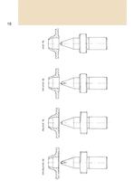
8a. short8b. short rem8c. short flat8d. short flat rem >
Open the catalog to page 20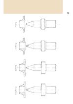
8e. long8f. long rem8g. long flat8h. long flat rem >
Open the catalog to page 21
7.1 Flowtapping 7.1.2 Example > The most common use of Flowdrills is to provide a high strength threaded fast- ener in thin sheet metal or tube. A Flowdrilled hole may be tapped with conventional cutting taps or preferably, with cold form Flowtaps. Flowtapping resembles Flowdrill except the opera- ting temperature is much lower; instead of cutting, Flowtaps cold-form the thread(no swarf). The diameter of the Flowdrill determines the final thread form,-depth and -strength. Tables in chap- ter 18.0 (back cover) show the recom-mended Flowdrill diameters for various thread sizes. M6 in 2 mm Fe 360Use...
Open the catalog to page 22
Soldered connection ( fig. 2f)Bearing support ( fig. 2e) fig. 2e fig. 2f >
Open the catalog to page 23
Non-ferrous metals (with the excep- tion of brittle material, like CuZn40Pb2). > Aluminium with less than 5% Si. > Stainless steel, acid resistant steel.In some cases it is desirable to test the suitability of the Flowdrill system. In particular in case of zinc coated mate- rials. >
Open the catalog to page 24
9.1Flowdrills are made of speciallydeveloped carbide. This will maintain its strength at high temperatures but is sensitive to thermal stress. Local cooling should be avoided.9.2Flowdrills cannot withstand highmechanical shock. They should not be dropped and hard impact onto the surface of the workpiece, as well as welded spots should be avoided.9.3Avoid radial forces on the Flowdrill 9.4Torsional stability of the Flowdrill is important. Too rapid release of torsional load caused by fast break through (very high feed rate) can cause fatigue.9.5A similar condition can occur due towind up if start...
Open the catalog to page 25
Flowdrill results depend on the mate-rial's physical properties, such as tensile strength, hardness, chemical content and conductivity. Generally all malle- able materials can be Flowdrilled. Lubrication of the Flowdrill can work against the need to generate heat but is required in small amounts to prevent pick-up or adhesion on the carbide surface, particularly when Flowdrilling aluminium. Flowdrill lubricants are spe-directly after Flowdrill operation. cially developed to meet this criterion. > Lubricate while Flowdrill is still running, > FDKS paste and FDKS fluid to use fordrilling in steel,...
Open the catalog to page 26All FLOWDRILL catalogs and technical brochures
 Leaflet
2 Pages
 ALUDRILL
1 Page
 Starterset
2 Pages
 Flow2Go
2 Pages
 Tool Holder
1 Page