Conveyor System XK
1 /20Pages
Conveyor System XK
1 /20Pages
Catalog excerpts

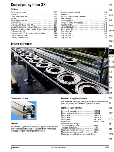
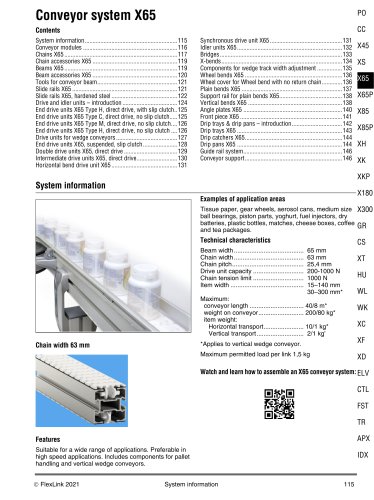
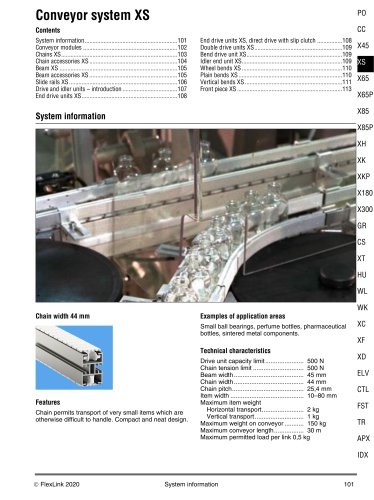
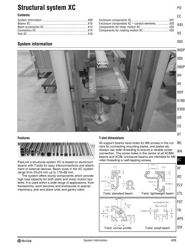
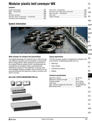
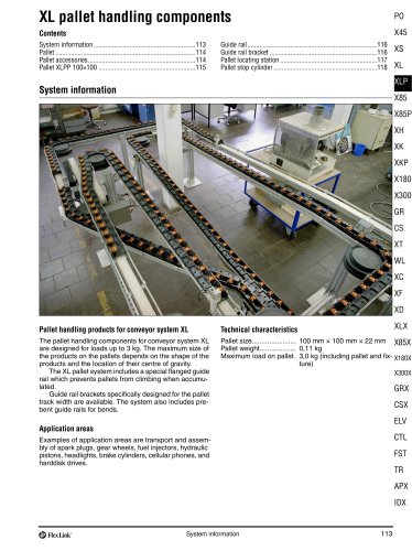
System information XH XK XKP X180 X300 GR CS XT WL WK Examples of application areas Suitable for larger items, especially if point of balance is somewhat offcenter. Higher capacity than other types. Includes components for pallet handling. Technical characteristics Ball and roller bearings, heavy boxes, gear wheels, motor parts on pallets, disk brakes, hydraulic pumps. System information
Open the catalog to page 1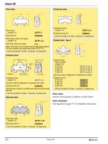
Plain chain Plain chain Plain chain (Ultra low wear) Plain link (Ultra low wear) Note. This chain must not be used in pallet applications. For this, please use closed top chain XKTP 5 A. *Link kit contains 10 links, 10 pivots, 10 steel pins Universal chain Universal chain Use the online configurator to specify and order. The link has a hole for an M6 screw. M6 nut will fit inside *Link kit contains 10 links, 10 pivots, 10 steel pins *Link kit contains 10 links, 10 pivots, 10 steel pins *Link kit contains 10 links, 10 pivots, 10 steel pins Cleated chain, Type A Cleated chain Use the online configurator...
Open the catalog to page 2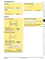
Plastic pivot Pin insertion tool for chain Beams XK Conveyor beam, standard Beam section for chain installation Beam, standard Length 3 m (3030 ±5 mm) Length to order (30- 3000 mm) Beam section for chain installation XKCC 200 Including connecting strips and screws Slide rail: see page 236 Profile for split conveyor beam XC Profile for split conveyor beam Length 3 m (3030 ±5 mm) Length to order (30- 3000 mm) Beam clip assembly Beam clip assembly Including M8 screw and locking nut. Use minimum 5 clips per meter. Place clips 100 mm from each end.
Open the catalog to page 3
Beam accessories XK Connecting strip with set screws Cover strip for T-slot, aluminium Connecting strip with set screws h=25, a=44, b=44, L=160 Cover strip for T-slot Aluminium, anodized Length 2 m Note. Must be ordered in multiples of 10 Cover strip for T-slot, PVC Cover strip for T-slot Grey PVC Length 3 m Beam spacer Aluminium, anodized Length 3 m For connection of two conveyor beams side to side. Use M8 screw and slot nut. Two holes must be drilled, one through the spacer (9 mm) and one through the beam, to allow insertion of the screw. The diameter of the second hole depends on the size...
Open the catalog to page 4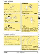
Slide rails XK (continued) Aluminium rivets Rivet crimping clamp Aluminium rivets 4 mm for XKX180/X300 conveyors, brown Extra slide rail in plain bends must be anchored using plastic screws due to lack of space for the rivet crimping tool. Note. Must be ordered in multiples of 250. Drill fixture for slide rail Drill fixture for X65-X85-XH-XKX180/X300 slide rail d=4,2 mm Rivet crimping clamp for X65-X85-XHXK-X180/X300 For 4 mm rivets (Allen key not included) Rivet crimping pliers Cover strip Length: 3 m Material: Plastic PA 12 Rivet crimping pliers for X65-X85-XHXK-X180/X300 For 4 mm rivets Cover...
Open the catalog to page 5
Slide rails, hardened steel XK (continued) Brass rivets 8 4 Rivets for anchoring the slide rails See Appendix B, page 469 for assembly instructions. Slide rail fixture 100 Slide rail fixture The fixture is used when anchoring the slide rail. Two fixtures are required. See Appendix B, page 469 for assembly instructions. Slide rails, hardened steel XK
Open the catalog to page 6
Drive and idler units – introduction Drive unit types Suspended motor, transmission chain, slip clutch Direct drive, slip clutch Suspended motor, transmission chain, slip clutch Catenary drive units Suspended motor, transmission chain, slip clutch X65P Motor specifications Motors are available for 230/400 V, 50 Hz and 230/460 V or 330/575 V, 60 Hz. All motors except those for Compact drive units can be connected for delta or star configuration by means of jumpers. Variable speed motors are SEW Movimot, 380–500 V. Note that variable speed motors include a control box that adds 93 mm to the width...
Open the catalog to page 7
End drive units XK End drive unit, suspended motor, slip clutch 80 End drive unit, suspended motor, slip clutch 80 End drive unit Suspended motor Fixed speed up to 60 m/min Transmission on left side Fixed speed * Without motor (ISO) Without motor (ANSI) XKEB XKEB 0 L XKEB 0 LA End drive unit, high capacity Suspended motor Fixed speed up to 25 m/min Transmission on left side Fixed speed * Without motor (ISO) Without motor (ANSI) XKEB XKEB 0 HL XKEB 0 HLA Maximum traction force: 1250 N. See page 23. *Use online configurator when ordering. Effective track length: 0,85 m Maximum traction force: 2500...
Open the catalog to page 8
End drive units XK, direct drive with slip clutch End drive unit, direct drive with slip clutch 270 End drive unit, direct drive with slip clutch 270 End drive unit, direct drive Fixed speed up to 60 m/min Variable speed: see Drive Unit Guide Motor on left side Fixed/variable speed * Without motor Maximum traction force: 1250 N. See page 23. *Use online configurator when ordering. Effective track length: 0,80 m End drive unit, direct drive Fixed speed up to 60 m/min Variable speed: see Drive Unit Guide Motor on right side Fixed/variable speed * Without motor Maximum traction force: 1250 N. See...
Open the catalog to page 9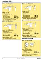
Catenary drive units XK Catenary drive unit, suspended 80 Catenary drive unit, suspended 80 Catenary drive unit Suspended motor Fixed speed up to 30 m/min Transmission on left side Fixed speed* Without motor (ISO) Without motor (ANSI) XKEC XKEC 0 L XKEC 0 LA Maximum traction force: 1250 N. See page 23. *Use online configurator when ordering. Effective track length: 1,60 m Catenary drive unit Suspended motor Fixed speed up to 30 m/min Transmission on right side Fixed speed* Without motor (ISO) Without motor (ANSI) Maximum traction force: 1250 N. See page 23. * Use online configurator when ordering....
Open the catalog to page 10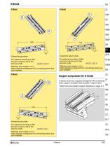
X-bend for top chain For optional mounting of Idler end unit or Drive unit at the end (A) or (B) For optional mounting of Idler end unit or Drive unit at the end (A) or (B) X-bend for return chain Effective track length: 3,3 m Note! Special arrangement for connecting beam support brackets Effective track length: 4,3 m Note! Special arrangement for connecting beam support brackets Support components for X-bends X-bends must have a special arrangement for connecting beam support brackets. See example in figure below. Read more about beam support brackets on page 317. X-bend for top chain For optional...
Open the catalog to page 11All FlexLink catalogs and technical brochures
 Conveyor system X180
14 Pages
 Conveyor system X85
32 Pages
 Conveyor system X65
28 Pages
 Conveyor system X45
52 Pages
 WLX222
16 Pages
 Food and dairy
8 Pages
 WLX
WLX2 Pages
 Enclosures and safety guards
158 Pages
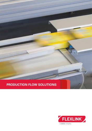 PRODUCTION FLOW SOLUTIONS
8 Pages
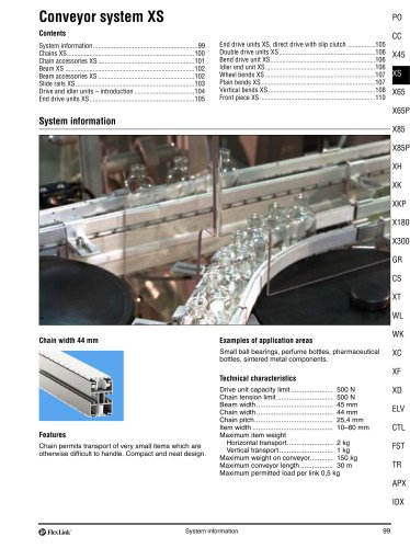
 Conveyor system XS
14 Pages
 Elevator
4 Pages
 Modular plastic belt conveyor WK
14 Pages
 Modular plastic belt conveyor WL
16 Pages
 Product overview
498 Pages
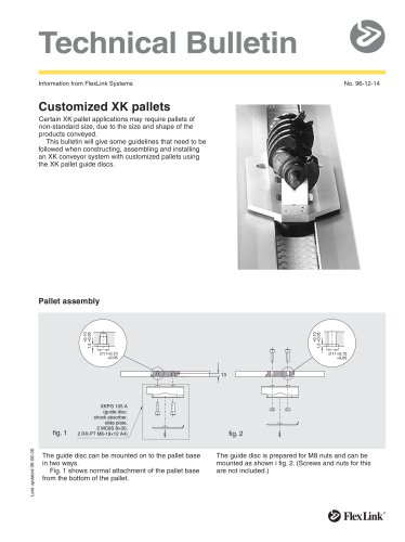 Customized XK pallets
2 Pages
 GENIUS PCB HANDLING SYSTEM
66 Pages
 Product Catalogue
160 Pages
 Conveyor system X300X
14 Pages
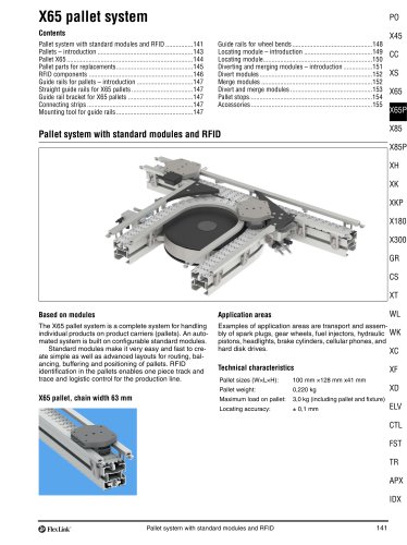 Pallet system X65
16 Pages
 Conveyor System WL
16 Pages
 Conveyor system WL374X
16 Pages
 Structural system XC
22 Pages
 Conveyor system X85X and X85Y
18 Pages
 Pallet system X85
22 Pages
 Configurable Components
20 Pages
 Product overview
24 Pages
 SMART PCB handling system
12 Pages
 GENIUS line
8 Pages
 SMART line
4 Pages
 Pallet system XTH
4 Pages
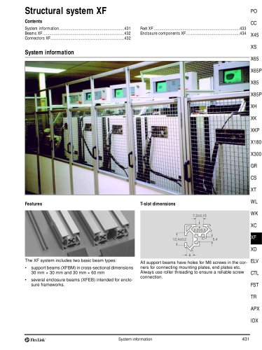 Structural system XF
8 Pages
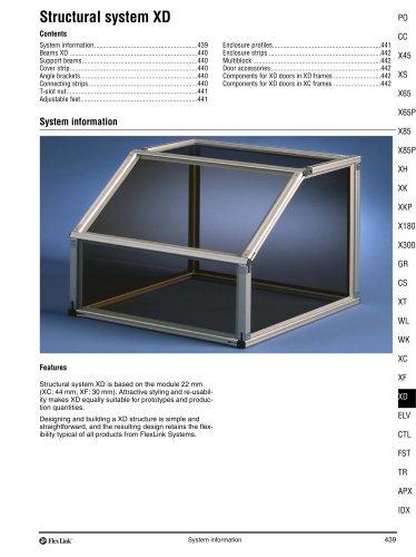 Structural system XD
4 Pages
 Spiral elevator
2 Pages
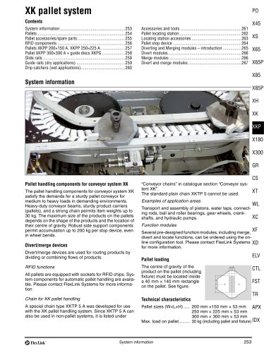 Pallet system XK
16 Pages
 Conveyor system WL526X
16 Pages
 Conveyor system XLX
8 Pages
 Pallet system XT
50 Pages
 Conveyor system WL678X
16 Pages
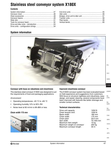 Conveyor system X180X
14 Pages
 Profile system MS+
320 Pages
 Conveyor system WK
12 Pages
 Conveyor system XW
20 Pages
 Conveyor System XH
20 Pages


Archived catalogs
 Conveyor System XS
12 Pages
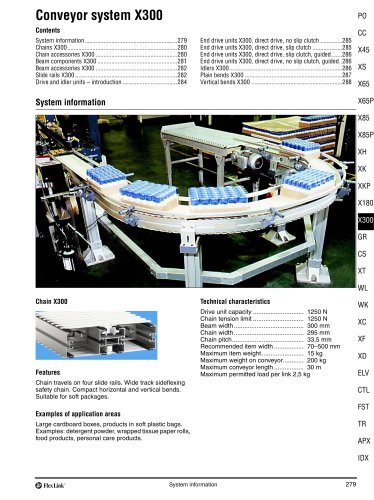 Conveyor System X300
10 Pages
 Conveyor System X180
10 Pages
 Conveyor System X85
34 Pages
 Conveyor system X65
32 Pages
 Conveyor System X65
30 Pages
 Conveyor System
52 Pages
 Conveyor System XL
28 Pages
- SARRALLE transport conveyor
- SARRALLE belt conveyor
- SARRALLE horizontal conveyor
- SARRALLE conveyor for the food industry
- SARRALLE chain conveyor
- SARRALLE handling conveyor
- SARRALLE palletizer
- Food conveyor
- Stainless steel conveyor
- SARRALLE modular conveyor
- SARRALLE robotic cell
- SARRALLE pallet conveyor
- Automatic conveyor
- Robotized palletizer
- Conveyor for the pharmaceutical industry
- Cardboard box conveyor
- Vertical conveyor
- SARRALLE box conveyor
- SARRALLE compact conveyor