
- Catalogs
- Flender GmbH
- FLENDER COUPLINGS


FLENDER COUPLINGS
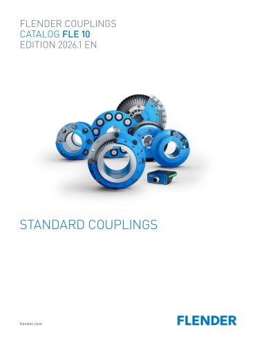
FLENDER COUPLINGS
Flender's catalog provides a comprehensive overview of standard couplings used in mechanical drive trains, detailing their role in connecting components like motors and gear units to facilitate rotary motion and torque transmission while compensating for shaft misalignment and controlling vibration.
- Torsionally Rigid Couplings: Includes N-ZAPEX and ARPEX, designed for rigidity in peripheral direction and flexibility in radial and axial directions.
- Flexible Couplings: N-EUPEX, RUPEX, and BIPEX use elastomer materials to absorb shaft misalignment.
- Highly Flexible Couplings: ELPEX series with large-volume elastomer elements for non-uniform torque applications.
- Fluid Couplings: FLUDEX couplings operate on the Föttinger principle for wear-free operation.
- Rigid Couplings: SKZF couplings are used where no shaft misalignment is permissible.
Details on shaft misalignment, balancing, and shaft-hub connections are provided, emphasizing proper alignment to prevent failures and outlining balancing standards according to DIN ISO 21940.
The AIQ Detect system offers continuous wear monitoring for N-EUPEX and RUPEX couplings using Hall sensors, providing real-time status updates via LED indicators and Bluetooth.
The selection process involves evaluating coupling series and size based on application requirements, including load conditions, speed, and environmental factors, with guidelines for checking maximum speed, shaft misalignment, and coupling design.
Flender's catalog offers a wide range of standard and application-specific couplings, ensuring optimal performance and reliability in various industrial applications.
Balancing quality is preset using an order code, with levels defined by DIN ISO 21940. Standard balancing options include maximum eccentricities of 100 μm, 40 μm, and 16 μm, with special balancing available on request.
Design of the machine shaft determines the bore and shaft-hub connection, with common connections including parallel keys, taper clamping bushes, and shrink-fit connections.
Relevant standards include the EC Machinery Directive, ATEX Directives, and various DIN and ISO standards for couplings and shaft-hub connections.
Key symbols and units are defined for parameters such as torsional stiffness, moment of inertia, misalignment, and torque, crucial for calculating torsional vibration and determining coupling performance.
Coupling series are selected based on criteria such as torque range, speed range, and operating temperature. The torque load is determined from the driven machine's output and coupling speed, adjusted by application factors.
Different elastomer materials used in couplings include NBR, HNBR, CR, and TPU, each with specific temperature ranges and performance factors.
Temperature factors are provided for different coupling materials and temperature ranges, affecting performance.
Maximum and overload torque conditions are outlined, with dynamic torque loads and frequency factors affecting permissible loads.
Maximum permissible speeds are specified, with adjustments for misalignment, and a speed correction factor is provided based on the misalignment angle.
Couplings are categorized as fail-safe or non-fail-safe, with recommendations for shaft-hub connections and environmental considerations.
Minimum operating temperatures and considerations for chemically aggressive environments are discussed, with manufacturer consultation recommended for specific conditions.
A configurator tool is available for selecting the appropriate coupling based on technical or direct selection methods.
Describes the N-ZAPEX XW series, highlighting its suitability for explosive atmospheres and compliance with ATEX directives, with benefits including high torque transmission and low maintenance requirements.
Detailed specifications for the N-ZAPEX XW series are provided, including rated torque, maximum speed, dimensions, and permissible misalignments.
Information on spare parts, such as plate packs, is provided, including dimensions, mass moments of inertia, and article numbers.
The ELPEX-S series of highly flexible couplings are designed for use in potentially explosive atmospheres, complying with the ATEX Directive, and are suitable for machines with non-uniform torque patterns.
The ELPEX-S couplings are available in 12 sizes with rated torques ranging from 330 Nm to 63,000 Nm, suitable for temperatures between -40 °C and +80 °C.
The rubber disk element is vulcanized onto a flange, with several types available, including ESN, ESD, ESNR, ESDR, ESNW, ESDW, and EST.
Materials used include grey cast iron, spheroidal graphite cast iron, steel, and cast aluminum, with rubber disk elements made from a natural-synthetic rubber mixture.
Includes rated torque, maximum torque, overload torque, fatigue torque, and dynamic torsional stiffness.
Outlines application factors for different torque characteristics and temperature factors, with details on maximum and overload torque conditions.
Depends on operating speed, with specific values provided for different sizes and speeds.
Designed to fit SAE J620d standard connection dimensions, with specific centering depths and flange connection sizes detailed.
Provides detailed specifications for the ELPEX series of highly flexible couplings, including rated torque, maximum torque, overload torque, fatigue torque, and dynamic torsional stiffness.
The correction factor (FKV) varies with speed, used in the calculation of Kperm.
Lists power ratings for different sizes, including rated torque, maximum torque, overload torque, and fatigue torque.
Couplings are available in cast iron and steel, with specific dimensions for each material type.
Instructions for ordering include specifying bore diameters and keyway dimensions according to DIN 6885.
Highlights the importance of considering the application factor FB in the coupling selection process.
Outlines the specifications for highly flexible couplings, specifically the ELPEX and FLUDEX series, with details on rated torque, maximum speed, and dimensions.
For identifying complete item numbers and available finish boring options, users are directed to use configurators on flender.com.
The flange connection dimensions adhere to SAE J620d or DIN 6288 standards.
FLUDEX couplings are recommended for use in conveyor systems, heavy industry applications, and drives with diesel engines.
Includes technical specifications for the FLUDEX series, detailing the design, configurations, and function based on the Föttinger principle.
Provides detailed information on the dimensions, weight, and inertia of various coupling sizes.
FLUDEX couplings feature thermal switching equipment and optional temperature monitoring systems.
FLUDEX couplings are balanced to quality G6.3 for 1800 rpm, with micro-balancing available for higher speeds.
FLUDEX couplings with fusible safety plugs are suitable for potentially explosive atmospheres as per ATEX Directive 2014/34/EU.
FLUDEX couplings come in various series and types, characterized by different flow chamber configurations and delay chambers.
Different series offer varying starting characteristics, with FA series as basic couplings driven via the hollow shaft.
FLUDEX couplings are used for starting aids, torsional vibration isolation, and overload limitation.
The size is determined by the output to be transmitted, with no additional safety factors required.
- Hollow Shaft: Bore ØD1 = 60H7 mm with keyway to DIN 6885/1 and retaining screw.
- Oil Filling: Quantity specified as 7.6 liters for certain configurations.
- Article Numbers: Different configurations are identified by unique article numbers.
- Options for delivery with or without oil filling.
- Variants include finished or unfinished bores and additional features like brake drums or disks.
- Coupling weights are specified for maximum bores without oil filling.
- Oil filling delivery is only available for temperatures above -20°C.
- Type FAD: Includes N-EUPEX D add-on coupling.
- Type FAE: Features N-EUPEX E add-on coupling.
- Type FAM: Incorporates N-EUPEX M add-on coupling.
- Type FADB: Comes with N-EUPEX D add-on coupling and brake drum.
- Type FADS SB: Includes N-EUPEX D add-on coupling and brake disk for stopping brakes.
- Type FADS HB: Features N-EUPEX D add-on coupling and brake disk for blocking brakes.
Flange couplings are designed for heavily loaded shafts that experience shocks, alternating loads, and axial forces.
Torque is transmitted through shaft-hub connections, such as shrink fit or keyway connection, and secured by screw connections.
Provides detailed specifications for the SKZF series of rigid couplings, including rated torque, permissible speed, dimensions, mass moment of inertia, and weight for various sizes.
Provides an example for ordering a flange coupling SKZF, size 290, with specific bore dimensions and shrink fit for oil-hydraulic removal.
Recommendations for fitting include various tolerance assignments for different applications.
Includes fitting recommendations, deviation tables according to DIN ISO 286, and specifications for cylindrical shaft ends and parallel key connections.
References to related catalogs for different types of couplings and gear units.
Flender offers helical and planetary gear units suitable for various applications.
Flender provides a wide range of coupling solutions, including elastic, highly elastic, rigid, and hydrodynamic couplings.
Flender offers consultation services to help customers find the right drive system, along with a comprehensive service portfolio.
Flender provides application-specific solutions tailored to meet the unique requirements of various industries.
Flender offers solutions for a variety of industries, each with specific requirements.
Flender offers comprehensive support from planning to modernization, available globally 24/7.
Flender provides a range of services for gear units and couplings.
Further details on couplings, applications, gears, and services can be found on Flender's website.
Catalog excerpts
FLENDER COUPLINGS CATALOG FLE 10 EDITION 2026.1 EN STANDARD COUPLINGS flender.com FLENDER
Open the catalog to page 1
FLENDER STANDARD COUPLINGS Introduction Torsionally Rigid Gear Couplings Torsionally Rigid All-Steel Couplings N-ARPEX, ARPEX Flexible Couplings Fluid Couplings Rigid Couplings Highly Flexible Couplings
Open the catalog to page 3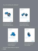
FLE 10 CATALOG GROUP FLENDER COUPLINGS CATALOG FLE 10.1 EDITION EN FLENDER COUPLINGS CATALOG FLE 10.3 EDITION EN TORSIONALLY RIGID COUPLINGS N-ZAPEX, N-ARPEX, ARPEX, SKZF HIGHLY FLEXIBLE COUPLINGS ELPEX-B, ELPEX-S AND ELPEX Product catalog FLE 10.1 FLEX-C10001-00-7600 Torsionally Rigid Couplings FLENDER COUPLINGS CATALOG FLE 10.2 EDITION 2024.1 EN FLENDER COUPLINGS CATALOG FLE 10.4 EDITION EN FLEXIBLE COUPLINGS N-EUPEX, RUPEX AND BIPEX FLUID COUPLINGS FLUDEX Product catalog FLE 10.2 FLEX-C10001-00-7600 Flexible Couplings For further coupling catalogs, see page A/6 E/2 Product catalog FLE 10.3...
Open the catalog to page 4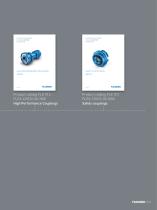
FLENDER COUPLINGS CATALOG FLE 10.5 EDITION EN FLENDER-COUPLINGS CATALOG FLE 10.7 EDITION EN HIGH PERFORMANCE COUPLINGS ARPEX SAFETY COUPLINGS ARPEX Product catalog FLE 10.5 FLEX-C10120-00-7600 High Performance Couplings Product catalog FLE 10.7 FLEX-C10122-00-7600 Safety couplings
Open the catalog to page 5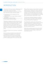
FLENDER STANDARD COUPLINGS | INTRODUCTION INTRODUCTION The mechanical drive train comprises individual units such as motor, gear unit and driven machine. The coupling connects these component assemblies. As well as the transmission of rotary motion and torque, other requirements may be made of the coupling. • Compensation for shaft misalignment with low restorative forces • Control of characteristic angular vibration frequency and damping • Interruption or limitation of torque • Noise insulation, electrical insulation Couplings are frequently chosen after the machines to be connected have already...
Open the catalog to page 6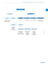
FLENDER STANDARD COUPLINGS | INTRODUCTION Clutches rigid flexible I Gear couplings All-steel membrane couplings Universal-joint couplings Parallel-crank couplings Steel-spring couplings Pin-and-bush couplings Pin couplings Rubber element couplings Rubber-tire couplings Rubber-disk couplings Rubber spacer ring couplings
Open the catalog to page 7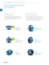
FLENDER STANDARD COUPLINGS | INTRODUCTION OUR COUPLING GROUPS AT A GLANCE E 4 N-EUPEX, RUPEX and BIPEX ELPEX, ELPEX-B and ELPEX-S Flexible Flender couplings have a wide range of possible applications. A broad standard modular system as well as specially designed applicationspecific couplings are available. ELPEX® couplings are free of circumferential back-lash. Their damping capacity and low torsional stiff-ness make them especially well-suited for coupling machines with strongly non-uniform torque characteristics or large shaft misalignment. Flexible Couplings Highly Flexible Couplings ELPEX...
Open the catalog to page 8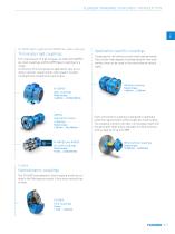
FLENDER STANDARD COUPLINGS | INTRODUCTION E N-ZAPEX gear couplings and ARPEX all-steel couplings Torsionally rigid couplings For transmission of high torques, we offer both ARPEX all-steel couplings and N-ZAPEX gear couplings in a range of versions. Their purposes of application vary according to specific requirements with respect to shaft misalignment, temperature and torque. Application-specific couplings Couplings for rail vehicles must meet high demands. Due to their high degree of standardization and wide variety, they can be used in the most diverse vehicle types. Railway coupling N-ZAPEX...
Open the catalog to page 9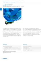
FLENDER STANDARD COUPLINGS | INTRODUCTION The AIQ Detect uses several Hall sensors to determine the wear on the flexible Flender couplings of the N-EUPEX and RUPEX via sensor magnets installed on the coupling side. The progressive wear of the elastomer components of the RUPEX and N-EUPEX results in a torsion angle between the coupling halves. This angle of rotation and the resulting time difference between the coupling halves make it possible to detect the degree of wear of the RUPEX and N-EUPEX flexible couplings. The speed of the coupling is also determined. This information can be evaluated...
Open the catalog to page 10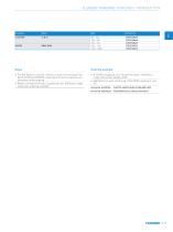
FLENDER STANDARD COUPLINGS | INTRODUCTION Notes Ordering example • The AIQ Detect is used for continuous wear monitoring of Ften-der N-EUPEX and RUPEX couplings and can be ordered as an accessory to the coupling • Make sure that the Ftender coupling has the ‘AIQ Detect-ready' status (see ordering example) • N-EUPEX coupling A, size 110 with the status "AIQ Detect-ready" (Article No. addition A99) • AIQ Detect for wear monitoring of N-EUPEX coupling A, size Article No. N-EUPEX: 2LC0170-4AB99-0AA0-Z L0M+M0P+A99 Article No. AIQ Detect: F2E01528467 (according to the table)
Open the catalog to page 11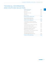
FLENDER STANDARD COUPLINGS | INTRODUCTION TECHNICAL INFORMATION AND COUPLING SELECTION Technical information Shaft misalignment Shaft-hub connections Selection of the coupling series Typical coupling solutions for different example applications Selection of the coupling size Coupling load in continuous operation Coupling load at maximum and overload conditions Coupling load due to dynamic torque load Checking the maximum speed Checking permitted shaft misalignment Checking bore diameter, mounting geometry and coupling design Coupling behavior under overload conditions Checking shaft-hub connection...
Open the catalog to page 13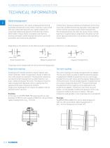
FLENDER STANDARD COUPLINGS | INTRODUCTION Shaft misalignment Shaft misalignment is the result of displacement during assembly and operation and, where machines constructed with two radial bearings each are rigidly coupled, will cause high loads being placed on the bearings. Elastic deformation of base frame, foundation and machine housing will lead to shaft misalignment which cannot be prevented, even by precise alignment. Furthermore, because individual components of the drive train heat up differently during operation, heat expansion of the machine housings causes shaft misalignment. Poorly...
Open the catalog to page 14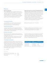
FLENDER STANDARD COUPLINGS | INTRODUCTION Balancing Balance quality levels The so-called quality level G to DIN ISO 21940 indicates a range of permitted residual imbalance from zero up to an upper limit. Applications can be grouped on the basis of similarity analysis. For many applications a coupling balance quality of G 16 is sufficient. On drives susceptible to vibration the balance quality should be G 6.3. Only in special cases is a better balance quality required. Balancing standard in accordance with DIN ISO 21940-32 Besides the required balance quality, it is necessary to set standards...
Open the catalog to page 15All Flender GmbH catalogs and technical brochures
 UNLIMIT YOUR GEARBOX
12 Pages
- Electric gearmotor
- Planetary gearbox
- Coaxial gearhead
- Precision gearhead
- Right angle gearhead
- Compact gearhead
- Gear train gear reducer
- Gearbox for industrial applications
- Transmission gearhead
- Multi-stage gearhead
- Coaxial gearmotor
- Right angle electric gearmotor
- AC gear-motor
- Planetary gearmotor
- Helical gear gearhead
- Machines gearbox
- Dual-stage gearbox
- Low-noise gearhead