
- Catalogs
- Fixtureworks
- Spring Clamps

- Company
- Products
- Catalogs
- News & Trends
- Exhibitions
Spring Clamps

Spring Clamps
Overview
This document provides detailed technical specifications, ordering information, and usage guidelines for various types of spring clamps, hold-down clamps, clamping spindles, thrust clamps, and clamping bars available from Fixtureworks. It includes product dimensions, clamping forces, materials, and installation notes, along with references to CAD downloads and pricing available on the supplier's website.
1. Spring Clamps
Spring clamps are offered in multiple sizes and configurations (right-hand and left-hand versions). Key parameters include dimensions (length, height, width), thread sizes (M4, M5, M8), clamping force ranges (e.g., 150-210N for QLSWC18R-18), and weight. The clamps feature clockwise (CW) or counterclockwise (CCW) handle operation. The document provides minimum and maximum dimensional tolerances for critical features.
2. Vertical-Handle Hold-Down Snap Clamps (Mini)
These clamps are available in stainless steel and other finishes, with model numbers such as QLSNDM08 and QLSNDM12. Clamping forces vary by model, with forces larger than 10N or 30N depending on the variant. Detailed dimensions include thread sizes (M8, M12), handle lengths, and incomplete thread lengths. Usage notes emphasize proper handle positioning for optimal clamping.
3. Vertical-Handle Hold-Down Snap Clamps (Standard)
Models like QLSND28-02 and QLSND30-03 are described with dimensions, clamping forces (20N to 60N), and thread specifications. Extension arms (e.g., QLSND-EX20) are available to increase clamping force. Angular adaptors (QLSND-AN10) allow for installation at specific angles (30° to 60°), enhancing versatility.
4. Push-Pull Snap Clamps
Push-pull style snap clamps (models QLSNS28-05, QLSNS30-07) are detailed with clamping forces ranging from 50N to 140N. Dimensions and handle angle recommendations are provided to ensure correct installation and operation. Related products and accessories are referenced for extended functionality.
5. Clamping Spindles
Clamping spindles (UB series) come in mini, standard hold-down, and push-pull types with various thread sizes (M4, M5, M6) and lengths. Dimensions such as spindle diameter, thread pitch, and overall length are specified. Installation examples are included to guide proper assembly.
6. Thrust Clamps
Thrust clamps (QLRC series) provide clamping forces from 0.2kN to 1.4kN. Both left-hand and right-hand versions are available with clockwise and counterclockwise handle operation. Detailed dimensions include body size, thread specifications, and stroke lengths. The document also covers thrust clamps with vertical handle variants (QLRCF series) with similar force ratings and dimensional data.
7. Clamping Bars
Clamping bars (QLRCS series) are designed for precision clamping with aluminum anodized bodies and steel linkage knobs. Clamping forces range from 55N to 175N depending on the model. The bars feature fast stroke and clamping stroke specifications, with detailed dimensional data for mounting and operation. The handle includes a clicking feature to indicate completed clamping, and the handle is replaceable when attachments are installed.
8. Technical Notes and Usage Recommendations
- Handles are designed to click upon full clamping to provide tactile feedback.
- Proper handle positioning is critical for achieving recommended clamping forces.
- Attachments for clamping bars allow for specialized applications such as conduction testing and press-fit fixtures.
- Allowable load, deflection, rotation torque, and rotation accuracy parameters are provided to ensure reliable and precise clamping performance.
9. Ordering and CAD Resources
All products include references to pricing, ordering, and CAD downloads available at fixtureworks.com, facilitating easy integration into design and procurement workflows.
Contact Information
For further inquiries, contact Fixtureworks at 33792 Doreka Dr., Fraser, MI 48026, phone 586-294-1188, or email [email protected].
Catalog excerpts

Spring Clamps
Open the catalog to page 1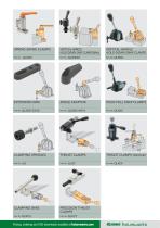
ANGLE ADAPTOR Pricing, ordering and CAD downloads available at fixtureworks.com
Open the catalog to page 2
Pricing, ordering and CAD downloads available at fixtureworks.com
Open the catalog to page 3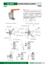
SPRING SWING CLAMPS RrmjJC w 11J ★Key Point -[ Handle clicks at the clamping end point. ^ Body Pricing, ordering and CAD downloads available at fixtureworks.com
Open the catalog to page 4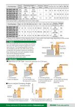
*)Clamping height is adjustable within the listed range. Part Number **) Values at the midpoint of the clamping stroke. It varies within the listed range depending on the contact point of the clamping spindle that decides the spring tension. Feature ■Turn the handle after the arm swings into position, the cam shaft rotates along the guide pin to push down the arm. The clamping spindle contacts the workpiece and the cam shaft moves up and compresses the spring to clamp the workpiece. ■ Easy clamping with one touch operation. Handle clicks at the clamping end point. ■Spring-loaded clamp provides...
Open the catalog to page 5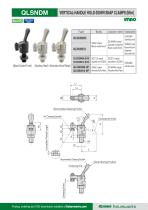
(Black Oxide Finish) (Stainless Steel) (Electroless Nickel Plated) VERTICAL-HANDLE HOLD-DOWN SNAP CLAMPS (Mini) fixture works Pricing, ordering and CAD downloads available at fixtureworks.com
Open the catalog to page 6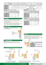
fixture works Pricing, ordering and CAD downloads available at fixtureworks.com
Open the catalog to page 7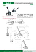
VERTICAL-HANDLE HOLD-DOWN SNAP CLAMPS Unclamping Mode ★Key Point [ The handle clicks at clamping end. Body Pricing, ordering and CAD downloads available at fixtureworks.com
Open the catalog to page 8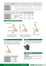
■The long handle facilitates clamping operation. ■The handle is locked at the unclamping position. ■Uses a snap-on system (double locking) ■|QLSND-EX20| Extension Arms to extend the clamp arm. ■IQLSND-AN10| Angle Adaptors to set the handle in an angled position. ■lUBlClamping Spindles to protect workpieces from being marred. fixture works Pricing, ordering and CAD downloads available at fixtureworks.com
Open the catalog to page 9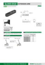
Dedicated for Snap Clamps Part Number Supplied With Hex. socket head setscrew M5X0.8-14L X2 pcs. S45C steel Black oxide Finish Clamping Forces Generated in Use of Extension Arms Part Number Pricing, ordering and CAD downloads available at fixtureworks.com fixture works
Open the catalog to page 10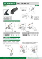
Part Number Hex.socket head cap screw M6X1 -12L X 1 pc. Remove the handle and then install an Angular Adaptor between the body and the handle. (Use a wrench of nominal size 9 for removal of the handle.) Perfect in applications where the handle can not be turned to the clamping position. fixture works Pricing, ordering and CAD downloads available at fixtureworks.com
Open the catalog to page 11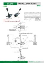
PUSH-PULL SNAP CLAMPS Clamping Mode ★Key Point -s[ The handle clicks at clamping end. ^ l_2 Pricing, ordering and CAD downloads available at fixtureworks.com
Open the catalog to page 12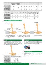
How To Set Handle To Recommended Clamping Position Part Number ■The long handle facilitates clamping operation. ■The handle is locked at the unclamping position. ■Uses a snap-on system (double locking) Related Product ■IQLSND-AN10I Angle Adaptors to set the handle in an angled position. ■lUBl Clamping Spindles to protect workpieces from being marred. fixture works Pricing, ordering and CAD downloads available at fixtureworks.com
Open the catalog to page 13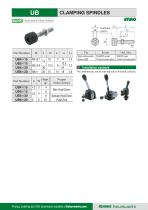
CLAMPING SPINDLES RrmjJC w 11J Part Number Part Number Installation example The urethane tip avoids marring soft or finished surfaces. Pricing, ordering and CAD downloads available at fixtureworks.com fixture works
Open the catalog to page 14
Pricing, ordering and CAD downloads available at fixtureworks.com
Open the catalog to page 15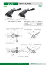
THRUST CLAMPS RrutUC w/ i tD Light-Duty Heavy-Duty(Marked with Blue Arrow) (Marked with Black Arrow) Note: Clamping bar is not included. Pricing, ordering and CAD downloads available at fixtureworks.com ^imno fixture works
Open the catalog to page 16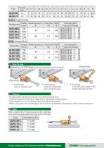
Pricing, ordering and CAD downloads available at fixtureworks.com
Open the catalog to page 17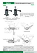
THRUST CLAMPS (Vertical) RrmjJC w 11J Pricing, ordering and CAD downloads available at fixtureworks.com
Open the catalog to page 18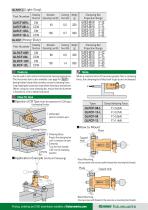
Part Number QLRCFl(Heavy-Duty) Part Number ■Can be used in both vertical and horizontal clamping applications. ■The horizontal style is also available, (see page for IQLRCI) ■Spring-loaded clamp that provides constant clamping force. ■ Long clamping-bar projection range allows clamping a recessed part. (When using your own clamping bar, ensure that the diameter is finished to a h9 or better tolerance) When a reaction force (F) becomes greater than a clamping force, the clamping bar slides back to get a part undamped. ■ Operation of CW Type (Invert the operation for CCW type.) Unclamping Position...
Open the catalog to page 19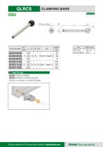
CLAMPING BARS RrmjJC w 11J Pricing, ordering and CAD downloads available at fixtureworks.com
Open the catalog to page 20
Pricing, ordering and CAD downloads fixtureworks.com Pricing, orderingavailable and CADatdownloads available at fixtureworks.com
Open the catalog to page 21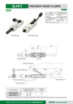
PRECISION THRUST CLAMPS RrmjJC w 11J Part Number *) The minimum clamping force at clamping end position, and the maximum clamping force at clamp starting position. Pricing, ordering and CAD downloads available at fixtureworks.com fixture works
Open the catalog to page 22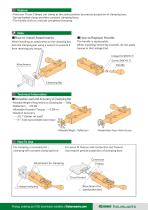
■Precision Thrust Clamps can clamp at the same position by precise projection of clamping bars. ■Spring-loaded clamp provides constant clamping force. ■The handle clicks to indicate completed clamping. ■ How to Install Attachments When installing an attachment on the clamping bar, lock the clamping bar using a wrench to prevent it from receiving any torque. When installing/removing a handle, do not apply torque to the Linkage End. ■Allowable Load and Accuracy of Clamping Bar ■Allowable Weight of Attachments on Clamping Bar ■ ■ -500g ■Deflection - ■ -±0.05 ■Allowable Rotation Torque ■ ■ -0.5N-m...
Open the catalog to page 23
Pricing, ordering and CAD downloads available at fixtureworks.com
Open the catalog to page 24All Fixtureworks catalogs and technical brochures
 Sliding Locks
41 Pages
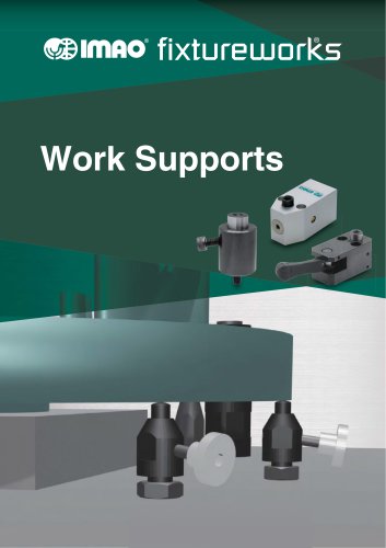 Work Supports
24 Pages
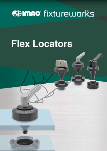 Flex Locators
41 Pages
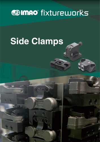 Side Clamps
27 Pages
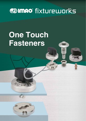 One Touch Fasteners
138 Pages
 One Touch Clamps
68 Pages
 QCTH / QCTHL / QCTHH
4 Pages
 QCSL
QCSL4 Pages
 QSC
QSC2 Pages
 QCPC
QCPC4 Pages
 QCTH-N / QCTH-B
2 Pages
 Fixtureworks catalog
572 Pages
 ROLLERS
30 Pages
 INDEXING PLUNGERS
13 Pages
 CMM_Inspection
10 Pages
 BUMPERS
14 Pages
 TRIMAX VISES
40 Pages
 SPRING & BALL PLUNGERS
16 Pages
 KNOBS
KNOBS27 Pages
 ADJUSTABLE HANDLES & LEVERS
37 Pages
 CLAMPS
72 Pages
 QUICK RELEASE BALL LOCK PINS
62 Pages
 Pull Handles
9 Pages
 MACHINE ACCESSORIES
8 Pages
 HAND WHEELS & CRANK HANDLES
25 Pages


