
- Catalogs
- Fixtureworks
- Pneumatic Clamps

- Company
- Products
- Catalogs
- News & Trends
- Exhibitions
Pneumatic Clamps
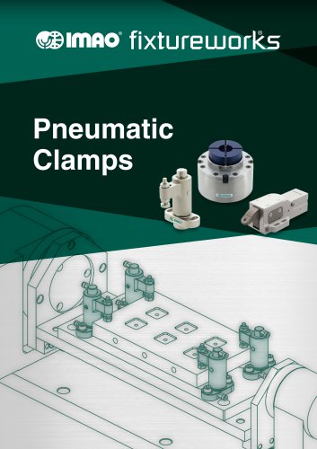
Pneumatic Clamps
Overview
This document details pneumatic air assisted clamps designed for automated manufacturing and fixture applications. These clamps use a wedge mechanism to convert pneumatic pressure into high mechanical clamping force, ensuring precise and secure workpiece fixation.
1. Product Features and Mechanism
- Wedge Mechanism: Converts air pressure into mechanical force via a tapered piston and wedge action for strong clamping.
- Customizable Jaws: Machinable jaws tailored to specific workpieces enhance grip and precision.
- Clamping Directions: Available in clockwise (CW) and counterclockwise (CCW) variants to fit various fixture designs.
- High Repeatability: Dual contact design achieves locating repeatability within 5 microns.
- Turbo Air Inlet: Optional turbo ports boost clamping force by supplying additional air pressure.
2. Model Variants and Specifications
Multiple clamp series are covered, each with detailed dimensional and performance data:
- AMWSW Series: Standard wedge clamps in sizes 16 and 20, with right and left hand versions.
- AMWSW-W-D Series: Variants with additional dimensional features for specialized mounting.
- AMWSW-W-AG and AMWSW-W-AC Series: Include detecting ports for clamp status monitoring, supporting gasket and threaded piping.
- AMWD-WS Series: Pneumatic hold down clamps for vertical clamping, with sensor bracket options.
- AMWPD-W Series: Pneumatic pull clamps with black oxide finish, body cylinders, and clamping pins for high force.
- AMWFH-WP Series: Pneumatic clamping modules with spring force and turbo air boost, ideal for quick change and form holding.
3. Technical Data and Performance
- Dimensions: Length, width, height, diameters, mounting hole sizes and positions.
- Clamping stroke and height specifications.
- Air port thread sizes and locations for clamping, unclamping, and detection.
- Operating air pressure typically 0.2 to 1.0 MPa, some models up to 1.3 MPa.
- Clamping force curves correlating force output to air pressure.
- Material finishes include black oxide and stainless steel for durability.
4. Usage Instructions and Best Practices
- Air Supply: Use clean, dry, filtered air to prevent malfunction.
- Installation: Adhere to specified mounting hole dimensions and orientations; use locating and diamond pins for precision.
- Operation: Clamping actuated by air pressure to clamping port; unclamping by releasing or supplying air to unclamping port.
- Detection Ports: Connect pressure sensors for automated clamp status feedback where available.
- Maintenance: Do not block turbo ports as they serve as air vents; install filters to avoid contamination.
5. Accessories and Related Products
- Sensor brackets for hold down clamps with magnet options for clamp/unclamp detection.
- Clamping pins and screws with detailed dimensions for compatibility.
- Optional jaws for external and internal form holding with precise locating features.
6. Application Examples
Illustrations demonstrate effective use of wedge mechanism clamps in various scenarios, emphasizing secure holding with high repeatability and force.
7. Critical Parameters Summary
- Operating Air Pressure: 0.2 to 1.0 MPa typical; some models up to 1.3 MPa.
- Clamping Force: From several hundred Newtons to over 1 kN depending on model and size.
- Mounting: Standardized hole sizes and spacing for easy fixture integration.
- Material: High-strength steel with black oxide or stainless steel finishes.
- Detection: Optional ports for pressure sensor integration enabling automated monitoring.
Mounting Hole Caps and Blow-out Function
Plastic caps protect module surfaces by covering mounting holes; installed by tapping with a plastic hammer and soft metal piece to avoid damage. For air blow function at clamp pin holes, replace caps with supplied orifice plugs. Removal uses a pointed tool. Rc1/8 external ports do not require plugs. Mounting hole spacing tolerance is ±0.02 mm.
Machining Accuracy and Mounting Hole Dimensions
| Part Number | d (G7) | h1 | D5 | D6 (H7) | D7 | h4 | h5 |
|---|---|---|---|---|---|---|---|
| AMWFH105-WP | 8 | 10 | 92 | 80 | 79.8 | 27 | 14 |
| AMWFH140-WP | 10 | 12 | 124 | 110 | 109.8 | 34 | 19 |
These dimensions are critical for correct mounting and machining accuracy.
Clamping Modules and Holding Force
| Part Number | Clamping Pin Size | Holding Force (kN)* | Fastened From Clamping Pin Top (Class 8.8 Screw) | Fastened From Fixture Plate Top (Class 12.9 Screw) |
|---|---|---|---|---|
| AMWFH105-WP | AMWFH105-M8 | 17 | 21 | |
| AMWFH140-WP | AMWFH140-M12 | 47 | 100 | |
| AMWFH140-M16 | 74 | 140 |
*Exceeding these holding forces may cause product or screw failure. Values measured at 0.6 MPa without safety factors.
Clamping Screws and Installation
Clamping screws (AMWPD series) come in various thread sizes (M8×1.25 to M16×2.0). Customers must prepare screws with lengths suited to fixture plate thickness. Workpiece locating pin spacing tolerance is ±0.2 mm.
Internal Pneumatic Connections and Multi-Module Actuation
Base plates must have channels for turbo, unclamping, and seating check air supply, connecting to vertical holes (φ2-4 mm). Minimum hole depths are specified to avoid interference with tapped holes. Unclamping and turbo hole depths can be reversed if necessary.
Clamping Pins
Made from SCM415 steel, carburized and hardened with black oxide finish. Types include Round (T), Diamond (D), and Non-Locating (S). Mounting hole tolerances: ±0.02 mm for locating pins, ±0.1 mm for non-locating pins.
Jaws for External Form Holding (AMWFH-O)
Constructed from anodized A7075 aluminum and black oxide S45C steel. Diaphragm clamping mechanism with 10 jaw sections tilting inward to clamp external forms. Allowable compression diameter: 0.6 mm. Workpiece locating repeatability ±0.03 mm; jaw locating repeatability ±0.02 mm. Installation involves clamping pin fixation, locking ring setting, jaw mounting, workpiece loading, and turbo air supply for clamping.
Jaws for Internal Form Holding (AMWFH-I) and Tapered Screws (AMWFH-IB)
Jaws made of anodized A7075 aluminum; tapered screws are SCM435 steel, quenched, tempered, and electroless nickel plated. Expansion via tapered screws actuated by turbo air supply clamps internal forms securely with 10 jaw sections. Allowable expansion diameter: 0.6 mm. Workpiece locating repeatability ±0.03 mm; jaw locating repeatability ±0.02 mm. Installation and operation similar to external jaws.
Additional Components and Accessories
- AMCH-W pneumatic clamping components with mounting instructions.
- AMNS-S pneumatic work supports with stroke and pressure specs.
- BJ370 series work supports mountable on top or bottom plate surfaces.
General Notes and Recommendations
- Do not actuate clamps without a workpiece to avoid damage.
- Use separate air supply ports for turbo and unclamping; plug unused ports with customer-prepared plugs.
- Maintain specified tolerances for hole spacing and pin mounting for proper function.
- Refer to fixtureworks.com for pricing, ordering, and CAD downloads.
Conclusion
The pneumatic air assisted clamps described provide robust, precise, and customizable solutions for automated clamping in industrial settings. Their wedge mechanism ensures high clamping force and repeatability, with multiple models and accessories supporting diverse fixture designs and automation needs.
Catalog excerpts

€&hmo* fixtureuuorks
Open the catalog to page 1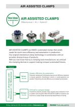
AIR ASSISTED CLAMPS [Mechanical + Air = Hybrid] AIR ASSISTED CLAMPS are IMAO's automated clamps that satisfy needs for much more efficiency and automation in production. Our original mechanical clamp technology in combination with air provides diverse lineup of products. With our own know-how as a clamping tools manufacturer, we unitized the clamping devices to support making compact automated fixtures. Greater efficiency by automation. Pneumatic clamping and unclamping improves work efficiency compared to manual operations. Simultaneous controls or remote-operations are possible. Productivity...
Open the catalog to page 2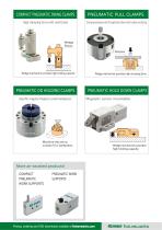
High clamping force with small body Wedge mechanism provides high holding capacity. PNEUMATIC HOLD DOWN CLAMPS More air-assisted products! COMPACT PNEUMATIC WORK PNEUMATIC SUPPORTS WORK SUPPORTS ^imno fixture uu orl<s
Open the catalog to page 3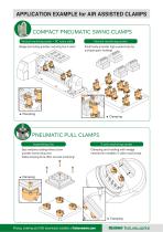
COMPACT PNEUMATIC SWING CLAMPS Vertical machining center Vertical machining center + NC rotary table PNEUMATIC PULL CLAMPS Assembling line Clamping and holding with wedge mechanism enables 5-sides machining! ^imao' fixture works Pricing, ordering and CAD downloads available at fixtureworks.com
Open the catalog to page 4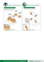
PNEUMATIC OD HOLDING CLAMPS Vertical machining center Horizontal machining center Less tool interference by low profile body! ^gimAO* fixture works Pricing, ordering and CAD downloads available at fixtureworks.com
Open the catalog to page 5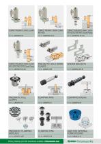
COMPACT PNEUMATIC SWING CLAMPS WITH ROD COMPACT PNEUMATIC SWING CLAMPS WITH DETECTING PORTS (Thread Piping) CLAMPING PINS CLAMPING PINS PNEUMATIC CLAMPING MODULES Pricing, ordering and CAD downloads available at fixtureworks.com ^mAO* fixtureujorks
Open the catalog to page 6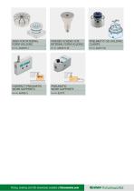
JAWS FOR INTERNAL FORM HOLDING TAPERED SCREWS FOR INTERNAL FORM HOLDING COMPACT PNEUMATIC WORK SUPPORTS PNEUMATIC WORK SUPPORTS Pricing, ordering and CAD downloads available at fixtureworks.com ®&imno fixtureujorks
Open the catalog to page 7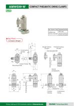
COMPACT PNEUMATIC SWING CLAMPS L1 L2 Rough Surface Contact Clamping Spindle Clamping Height Finished Surface Contact Clockwise Clamping Mounting Holes Pricing, ordering and CAD downloads available at fixtureworks.com Counterclockwise Clampi
Open the catalog to page 8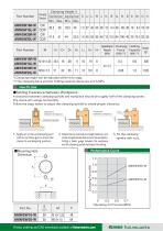
*) Clamping height can be adjusted within this range. **) The clamping force and the holding capacity above are at 0.5 MPa. ^imno' fixture uuorks Pricing, ordering and CAD downloads available at fixtureworks.com
Open the catalog to page 9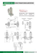
COMPACT PNEUMATIC SOWING CLAMP S WITH RO D i ★Key Point-[ Compact design! Dp Mounting Body/Clamp Arm/Piston Rough Surface Contact Finished Surface Contact Clamping Spindle Pricing, ordering and CAD downloads available at fixtureworks.com
Open the catalog to page 10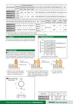
^imno' fixture works Pricing, ordering and CAD downloads available at fixtureworks.com Performance Curve
Open the catalog to page 11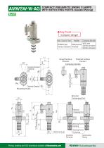
COMPACT PNEUMATIC SWING CLAMP WITH DETECTING PORTS (Gasket Piping) ★Key Point- [ Compact design! €&imno fixtureuuorks Pricing, ordering and CAD downloads available at fixtureworks.com
Open the catalog to page 12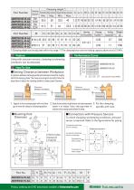
*) Clamping height can be adjusted within this range. **) The clamping force and the holding capacity above are at 0.5 MPa. Using with pressure sensors, clamping/unclamping conditions can be detected. A clearance between clamping spindle and workpiece should be roughly half of the clamping stroke. The clamp arm swings horizontally. Follow the steps below to adjust the clamping spindle to create proper clearance. 1. Apply air to the unclamping port with an air blow 2. Rotate the arm manually to straight direction, and create an appropriate 3. Fix the clamping gun to move the clamp to unclamping...
Open the catalog to page 13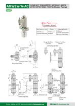
COMPACT PNEUMATIC SWING CLAMP WITH DETECTING PORTS (Thread Piping) ★Key Point-s [ Compact design! Body/Clamp Arm/Piston Pricing, ordering and CAD downloads available at fixtureworks.com €&imno fixtureuuorks
Open the catalog to page 14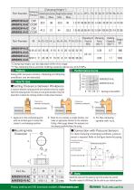
Part Number *) Clamping height can be adjusted within this range. **) The clamping force and the holding capacity above are at 0.5 MPa. Feature Performance Curve Using with pressure sensors, clamping/unclamping conditions can be detected. ■ Setting Clearance between Workpiece A clearance between clamping spindle and workpiece should be roughly half of the clamping stroke.The clamp arm swings horizontally. Follow the steps below to adjust the clamping spindle to create proper clearance. 1. Apply air to the unclamping port with an air blow gun to move the clamp to unclamping position. 2. Rotate...
Open the catalog to page 15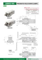
PNEUMATIC HOLD DOWN CLAMPS RrmJJC «r/11J ★One Point -[ Magnetic sensor mountable! Body Pricing, ordering and CAD downloads available at fixtureworks.com
Open the catalog to page 16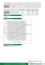
Supplied With *) The clamping forces above are at 0.5 MPa. Continuing on Next Page ^imao” fixture works Pricing, ordering and CAD downloads available at fixtureworks.com
Open the catalog to page 17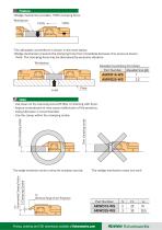
■The allowable counterforce is shown in the chart below. ■Wedge mechanism prevents the clamping force from immediate decrease if air pressure lowers. Note: The clamping force may be decreased by excessive vibration. Allowable Counterforce (Per Clamp) Pricing, ordering and CAD downloads available at fixtureworks.com
Open the catalog to page 18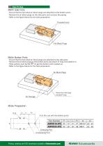
■Ensure that the furnished air block plugs are attached to the bottom ports. ■ Remove the air block plugs on the side ports and connect the piping. ■ Refer to the figure below for the hole preparation. HWith Bottom Ports ■Ensure that the furnished air block plugs are attached to the side ports. ■ Remove the air block plugsgon the bottom ports and attach O-rings (included) to it. ■Plate surface must be flat(v^)to get the bottom ports sealed up. ■ Refer to the figure below for the hole preparation. HHole Preparation 2-d2 (For use with the bottom ports) Part Number Pricing, ordering and CAD downloads...
Open the catalog to page 19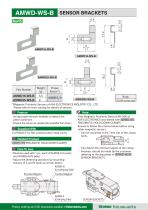
Part Number *)Magnetic Proximity Sensors of ASA ELECTRONICS INDUSTRY CO., LTD. Please refer to their catalog for details of sensors. ■Using proper sensors enables to detect the piston positions. ■ Prepare the sensors as needed.(Not available from Imao.) ■Only Magnetic Proximity Sensors AH-006 of ASA ELECTRONICS was tested with lAMWD-WSl PNEUMATIC HOLD DOWN CLAMPS. Supplied With 2 of M3x0.5-5L Hex socket button head screw lAMWD-WSl PNEUMATIC HOLD DOWN CLAMPS ■ Ensure to follow the criteria below before using other magnetic sensors. - Can be mounted in the 7mm slot of the clamp body. ■Must be used...
Open the catalog to page 20All Fixtureworks catalogs and technical brochures
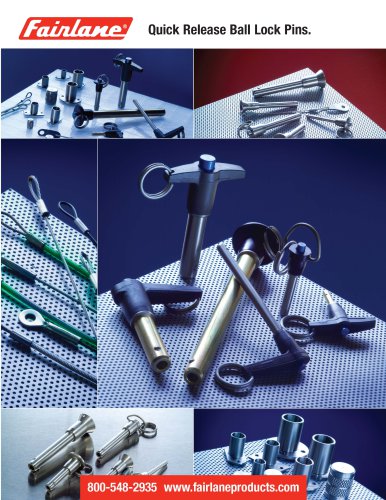 Quick Release Bail Lock Pins.
46 Pages
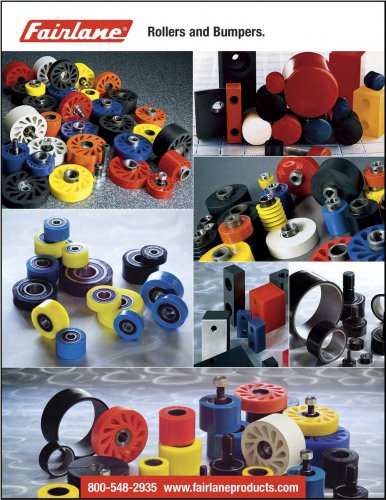 Rollers and Bumpers.
50 Pages
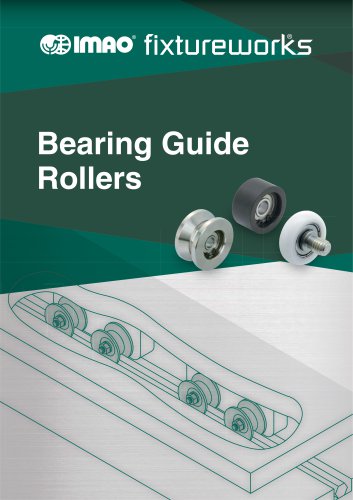 Bearing Guide Rollers
35 Pages
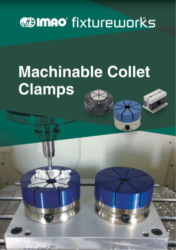 Machinable Collet Clamps
45 Pages
 Mechanical Linear Units
49 Pages
 5-Axis Clamping System
14 Pages
 Quick Shaft Clamps
15 Pages
 Torque Limiting Knobs & Handles
16 Pages
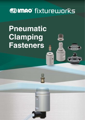 Pneumatic Clamping Fasteners
14 Pages
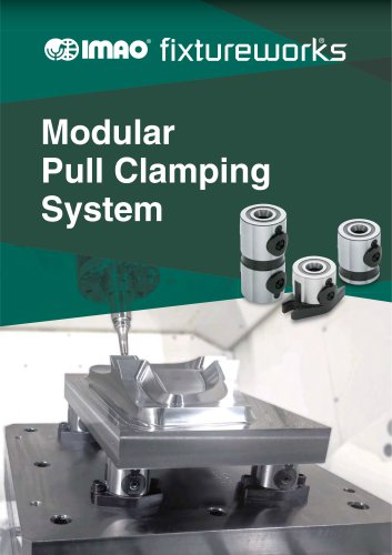 Modular Pull Clamping System
35 Pages
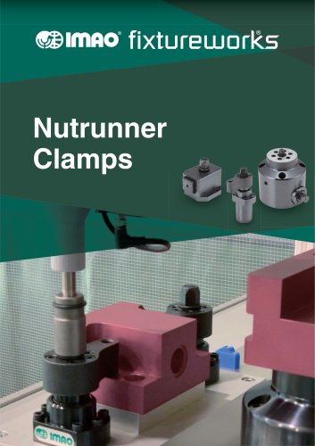 Nutrunner Clamps
24 Pages
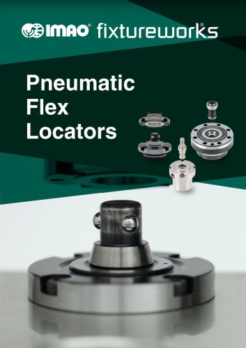 Pneumatic Flex Locators
23 Pages
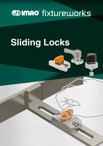 Sliding Locks
41 Pages
 Work Supports
24 Pages
 Flex Locators
41 Pages
 Spring Clamps
24 Pages
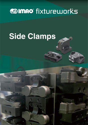 Side Clamps
27 Pages
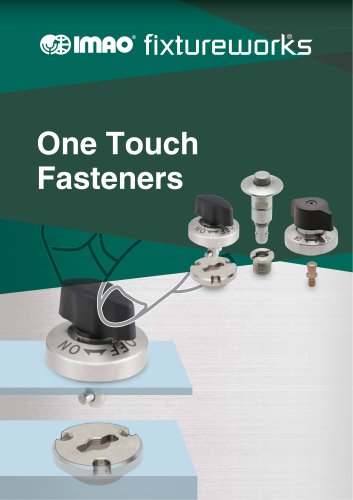 One Touch Fasteners
138 Pages
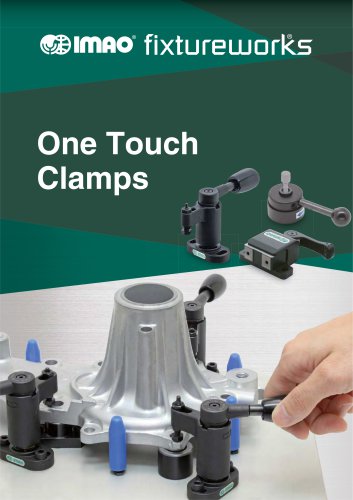 One Touch Clamps
68 Pages
Archived catalogs
 QCTH / QCTHL / QCTHH
4 Pages
 QCSL
4 Pages
 QSC
2 Pages
 QCPC
4 Pages
 QCTH-N / QCTH-B
2 Pages
 Fixtureworks catalog
572 Pages
 KNOBS
27 Pages
 SPRING & BALL PLUNGERS
16 Pages
 TRIMAX VISES
40 Pages
 BUMPERS
14 Pages
 CMM_Inspection
10 Pages
 ROLLERS
30 Pages
 INDEXING PLUNGERS
13 Pages
 ADJUSTABLE HANDLES & LEVERS
37 Pages
 QUICK RELEASE BALL LOCK PINS
62 Pages
 CLAMPS
72 Pages
 Pull Handles
9 Pages
 MACHINE ACCESSORIES
8 Pages
 HAND WHEELS & CRANK HANDLES
25 Pages


