- Company
- Products
- Catalogs
- News & Trends
- Exhibitions
Threaded insert tool manual AP4
1 /17Pages

Threaded insert tool manual AP4
1 /17Pages
Catalog excerpts

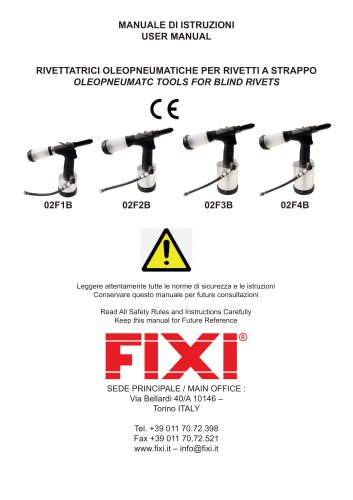
MANUALE D’ISTRUZIONE OPERATIONS MANUAL INSERTATRICE PNEUMO-IDRAULICA AIR - HYDRAULIC RIVETING TOOL MAIN OFFICE Via Bellardi, 40/A 10146 Torino - (Italy) Tel. +39 (0) 11 70.72.398 - F a x . +39 (0) 11 70.72.521 www.fixi.it - [email protected]
Open the catalog to page 1
1. ISTRUZIONI E PROCEDIMENTO GENERALE DI SICUREZZA ATTENZIONE! Leggere attentamente tutte le istruzioni. Chiunque installi, utilizzi o faccia manutenzione sull’attrezzo deve prima di tutto leggere questo manuale ed ha prima di tutto l’obbligo di seguire attentamente le seguenti istruzioni di sicurezza: - L’attrezzo non deve essere usato se non per le sue funzioni originali. L’attrezzo deve essere unicamente utilizzato nel modo raccomandato dal fornitore. Il cliente sarà pienamente responsabile degli eventuali adeguamenti effettuati sull’attrezzo, accessori e pezzi di ricambio forniti dal fornitore...
Open the catalog to page 3
2. DESCRIZIONE DELL’ATTREZZO 2.1 CARATTERISTICHE DI BASE 2.2 CARATTERISTICHE TECNICHE PESO KG. 1,65 PRESSIONE 0,5-O,7 MPa FORZA DI TRAZIONE A 0,6 MPa 18,5 KN CONSUMO DELL’ARIA 1,5 L/COLPO COLPO IN MASSIMA OPERATIVITA’ 7MM ALTEZZA 270 MM LUNGHEZZA 285 MM LARGHEZZA (ANGOLAZIONE DELLA VALVOLA) 99 MM
Open the catalog to page 4
2.3 UTILIZZO La rivettatrice ad aria compressa viene utilizzata per rivettare: - inserti filettati femmina M3-M12 (acciaio) inserti filettati maschi M4-M8 (acciaio) 2.4 FUNZIONAMENTO L’attrezzo viene fornito di con asta e testina per inserti M8. Per la rivettatura di rivetti con dimensioni differenti sarà necessario sostituire asta e testina e modificare la sistemazione e la regolazione di base dell’attrezzo come segue: 1) 2) 3) 4) Allentare il contro dado della testina /figura 1/ Svitare la testina dall’ugello /figura 1/ Svitare l’asta dal manicotto. Scegliere asta e testina in base alle dimensioni...
Open the catalog to page 5
9) Disporre la forza come segue: Inserto Per disporre la forza girare il manicotto di copertura dell’ugello. 10) Connettere l’attrezzo alla fonte di aria compressa. 11) Spingere l’inserto contro l’asta filettata, esso si avviterà automaticamente all’asta. 12) Disporre il rivetto nel foro. 13) Spingere il grilletto ed il rivetto verrà fissato. 14) Liberare il grilletto, l’asta filettata si sviterà dal rivetto (se non si sviterà completamente, utilizzare il pulsante /figura 1/). 15) Controllare il rivetto fissato: - Se il rivetto non è completamente fissato sarà necessario incrementa
Open the catalog to page 6
Se il rivetto è fissato eccessivamente, risulterà una eccessiva deformazione del rivetto e sarà difficilmente svitabile dall’asta filettata; in questo caso sarà necessario ridurre la forza. 16) L’attrezzo, sistemato secondo il metodo sopraindicato, è pronto per l’utilizzo. 3 MANUTENZIONE DELL’ATTREZZO Per la manutenzione dell’attrezzo è necessario disconnetterlo dalla fonte di aria compressa!! 3.1 MANUTENZIONE GIORNALIERA Giornalmente, prima della messa in opera dell’attrezzo, versare alcune gocce di olio (raccomandiamo olio idraulico HYSPIN AWHM 32 CASTROL) nella presa d’aria dell’attrezzo,...
Open the catalog to page 7
4.2 LISTA DEI RICAMBI PIU’ UTILIZZATI DESCRIZIONE Asta filettata per inserti M3 Asta filettata per inserti M4 Asta filettata per inserti M5 Asta filettata per inserti M6 Asta filettata per inserti M8 Asta filettata per inserti M10 Asta filettata per inserti M12 Testina M3 Testina M4 Testina M5 Testina M6 Testina M8 Testina M10 Testina M12 Ugello Manicotto 5 STOCCAGGIO La tirainserti va conservata nel contenitore di spedizione in un ambiente con umidità al 70% e temperatura che varia dai + 5°C ai + 40°C, lontana da aggressivi vapori di sale e acidi. 6 FUNZIONAMENTO E CONDIZIONI DI GARANZIA Si...
Open the catalog to page 8
6.2 CONDIZIONI DI GARANZIA Durante il periodo di garanzia, il cliente non è autorizzato a fare interventi sull’attrezzo, eccetto quelli concessi dal produttore (2.3-2.4). Il cliente deve mostrare il certificato di garanzia dell’attrezzo o la ricevuta, quando ricorre ad una riparazione in garanzia. La garanzia ha validità 24 mesi dalla data dell’acquisto confermata sul Certificato di garanzia, se nel contratto d’acquisto non è menzionata nessun’altra clausola. 7 CERTIFICATO DI GARANZIA CLIENTE:……………………………………………………………… firma e timbro FORNITORE:………………………………………………………… firma e timbro NUMERO SERIALE...
Open the catalog to page 9
1. GENERAL SAFETY INSTRUCTIONS AND POLICY ATTENTION! Read all the instructions carefully. Everyone who will install, operate or maintain the tool must read this manual at first and is obliged to follow these safety instructions: • The tool may not be used for other than its original purpose. The tool must be only operated in a way recommended by the producer The customer is fully responsible for any adjustments made on the tool, accessories or spare parts supplied by producer or its sales representatives. The producer provides professional help in case of planning or execution of further repair...
Open the catalog to page 11
W 2.3. Application Air-hydraulic riveting tool is intended for riveting: - screw rivets M4 – M8 (steel) 2.4. Operation of the tool The tool is equipped with a nose-piece and screw-plug gauge for nut rivet M8. For riveting of rivets with a different dimension it is necessary to exchange the nose-pieces and screw plug gauges and change basic set up and regulation of the tool as following: 1) Loosen the back nut of the nose-piece /pic. 1/ 2) Screw out the nose-piece from the nozzle /pic. 1/ 3) Screw out the screw-plug gauge from the sleeve 4) Choose appropriate nose-piece and screw-plug gauge according...
Open the catalog to page 13All FIXI catalogs and technical brochures
 BLIND RIVETS
52 Pages
 THREADED INSERTS
40 Pages
 SELF CLINCHING FASTENERS
44 Pages
 WELDING STUDS
40 Pages
 Fasteners for Plastic
44 Pages
 WIRE INSERTS
36 Pages
 INSERTS FOR TUBES
16 Pages
 Composites fastening systems
12 Pages
 Silicone Caps
4 Pages
 FIXI Products
4 Pages
 Battery powered riveter manuals
16 Pages