- Catalogs
- FIVES PILLARD
- A Air Motor with Auxiliary Switch
A Air Motor with Auxiliary Switch
1 /2Pages

A Air Motor with Auxiliary Switch
1 /2Pages
Catalog excerpts

North American 1600- -A Air Motor with Auxiliary Switch Bulletin 1600-A 1600- -A Air Motors are available for control systems that require auxiliary switches on the air motor or on the valve it drives. Such switches are used, for example, to prove air valve position for high flow purge and low fire start. 1600- -A Air Motors have two SPDT limit switches mounted in a NEMA 1 general-purpose enclosure. Each switch is actuated by a pair of manually adjustable cams driven off the end of the Air Motor shaft. One cam determines the "on" position of the switch; the other determines the "off" position. SETTING PROCEDURE 1. Remove the rear access cover from the switch housing. 2. With the burner on low fire, set Cam A (Fig. 1) to actuate the outer switch, closing the normally open circuit (Leads 1 and 2). 3. As the burner proceeds to high fire, adjust Cam A to open the circuit after about 5° of travel. 4. Cams B and C must be adjusted to avoid actuating their switches as the burner approaches high fire. Cams B and C can be used for other purposes, providing an adjustable dwell for each switch. 5. When the burner reaches high fire, adjust Cam D to actuate the inner switch, closing the normally open circuit (Leads 4 and 5). This switch should be actuated about 5° before the burner reaches high fire. Leads 4 and 5 of the inner switch are used as a normally open circuit to prove high fire. When this switch is actuated, the normally open circuit closes, proving high fire. Leads 3 and 6, when used with their respective common leads, provide a normally closed circuit in each switch for other application. #1 COMMON OUTER SWITCH CAM "D" #2 NORMALLY OPEN (circuit closed when burner is at low fire) #3 NORMALLY CLOSED (circuit open when burner is at low fire) Fig. 1. Adjustable cams and limit switches on Series 1600- -A Air Motor WIRING INSTRUCTIONS Leads 1 and 2 (Fig. 2) of the outer switch are used as the normally open circuit to prove low fire. When this switch is actuated, the normally open circuit closes, proving low fire. INNER SWITCH #5 NORMALLY OPEN (circuit closed when burner is at high fire) #6 NORMALLY CLOSED (circuit open when burner is at high fire) Fig. 2. Switch Wiring Diagram SWITCH RATINGS: 10 amp with 125 or 250 V ac; ½ amp with 125 V dc; ¼ amp with 250 V dc. Switch is UL and CSA listed. SWITCH WIRE is suitable for 105 C temperature and is UL listed. Switch leads are 12" lo
Open the catalog to page 1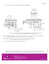
DIMENSIONS 1600- -A Air Motor. (For detail dimensions of 1600 Air motor, see Bulletin 1600.) Switch Housing Rear Access Cover Tapped hole in end of lever shaft DIMENSIONS SHOWN ARE SUBJECT TO CHANGE. PLEASE OBTAIN CERTIFIED PRINTS FROM FIVES NORTH AMERICAN COMBUSITON, INC. IF SPACE LIMITATIONS OR OTHER CONSIDERATIONS MAKE EXACT DIMENSION(S) CRITICAL. 1600- -A Switch Kit Assemblies are available for field assembly to 1600 Air Motors (built since 1972--such motors can be identified by a drilled and tapped hole in the end of the lever shaft opposite the lever (see sketch)). To Order, Specify: 1600-...
Open the catalog to page 2All FIVES PILLARD catalogs and technical brochures
 Pillard LM3086 SE
2 Pages
 Pillard Windcross™
2 Pages
 Pillard Nocostop Eco
2 Pages
 Pillard Nocostop Premium™
2 Pages
 Pillard Opastop® GP4000T-EX
2 Pages
 Pillard Opastop® GP4000H-EX
2 Pages
 Pillard Dieselight™
2 Pages
 Pillard Opastop® GP4000H
2 Pages
 Pillard Opastop® GP4000H-C
2 Pages
 Pillard DarkscanFlex™
2 Pages
 Pillard Oxycheck™
2 Pages
 Pillard Packlight™
2 Pages
 Pillard flame scanners
4 Pages
 Pillard Smokecheck™
2 Pages
 Pillard Powerpack™
2 Pages
 Pillard Windcheck™
2 Pages
 Pillard Powerpack™
2 Pages
 OPASTOP GP4000H-EX
2 Pages
 Pillard TK Drain
2 Pages
 INDUCTFLAM® L
2 Pages
 OPAGAZ
2 Pages
 Pillard RotaFlam®
2 Pages
 Pillard PrecaFlam™
2 Pages
 Pillard NovaFlam®
2 Pages
 Blower Silencers
2 Pages
 Series 2300 Turbo Blowers
7 Pages
 SAF – Adjustable Flow Valve
2 Pages
 Limiting Orifi ce Gas Valves
3 Pages
 Double Shutoff Valve
2 Pages
 Oil Shutoff Valves
6 Pages
 Pneumatic Cycle Valve
2 Pages
 Air Cycling Valve
2 Pages
 Wafer Butterfly Valves
4 Pages
 1008A-C / 1010A-C-1
3 Pages
 Adjustable Port Valves
4 Pages
 Butterfl y Valves
4 Pages
 ITAS Ductflame
4 Pages
 ITAS Speedflame
4 Pages
 ITAS Dryflame
4 Pages
 ITAS Intensityflame
4 Pages
 Adjustable Port Valves
2 Pages
 Waste heat recovery
48 Pages
 Pillard Opastop® GP3050ST
2 Pages
 Pillard SmokecheckTM
2 Pages
 Pillard Windcheck™
2 Pages
 Pillard NocostopTM
2 Pages


Archived catalogs
 Pillard Packlight
2 Pages
 Pillard flame scanners
4 Pages
- Gas analyzer
- Management software solution
- Concentration analyzer
- Monitoring analyzer
- Liquids analyzer
- Pressure limiter
- Real-time software
- Solids analyser
- Monitoring software solution
- Industrial software
- Continuous analyzer
- Real-time analyzer
- Oxygen analyzer
- Industrial detector
- Gas pressure limiter
- Calibration analyzer
- Monitoring detector
- Waterproof analyzer
- Temperature analyzer
- RS485 analyzer