- Catalogs
- FIVES PILLARD
- 1177D-EP2 Control Valves for Air and Exhaust
1177D-EP2 Control Valves for Air and Exhaust
1 /5Pages

1177D-EP2 Control Valves for Air and Exhaust
1 /5Pages
Catalog excerpts
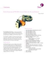
North American 1177D-EP2 Control Valves for Air and Exhaust Bulletin 1177D-EP2 The 1177D-EP2 Control Valve is a electro-pneumatically controlled butterfly valve capable of handling fluids up to 800 degF. For control input the valve uses a 4-20mA signal, and also features a feedback unit with 4-20mA output . The 1177D-EP2 is capable of a full open-close-open cycle in less than 2 seconds for all sizes. This makes it ideal for applications which require a fast acting valve. The valve seats against machined seats in the body to prevent overtravel and provides a low leak rate. (See table 1). INSTALLATION All 1177D-XX-EP2 Valves must be installed with the shaft in a horizontal orientation. Maximum ambient temperature must not exceed 176 degF. See sheet “1177D Dimensions” for process and control connection information. See sheet “Supply Air Requirements 1177D-EP2/1008-EP2” for air quality information. Each valve is supplied with a 1/4" miniature .01 micron automatic pulse drain coalescing filter to be installed in the compressed air supply line. Required supply air pressure is 70-90 psig. Valve Body Material: Heat Resistant Cast Iron — Valve Disc Material: 316 SS — Valve Shaft Material: 316 SS — — Disc Clamp Material: 316 SS Disc Clamp Hardware: 304 SS — Compressed Air Supply Pressure: 70-90 psig — Maximum Operating Pressure: 2 psig — Wafer Style Design — — -6 thru -14 ANSI class 150 flange — -16 RPM flange Maximum Fluid Temperature: 800 degF — Maximum Ambient Temperature: 176 degF — — Minimum Ambient Temperature: -4 degF Actuator Cycle Rating (closed to open to closed): — 1,000,000 Max Travel Time (open-close-open): 2 seconds — Position Indication: Visual Indication on positioner — — Input 4-20mA — 4-20mA Position Transmitter — 10-30 VDC (24 VD
Open the catalog to page 1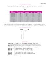
CAPACITY INFORMATION Flow is rated in SCFH, 70% open with a 1"wc drop at 70 degF. and 14.7 PSIA. Leak rate is rated in SCFH with 1 PSI backpressure. Change in flow and pressure drop across the valve is negligible when changing from 70% open to wide open unless inlet pressure is increased substantially to maintain the 1" wc pressure drop, which is why the sizing table shows capacities at 70% open. ORDERING INFORMATION SPARE PARTS SPARE AND REPLACEMENT PARTS LIST FOR EP2 SERIES VALVES Digital positioner, 4-20mA input/output, Namur mount, includes gauge block 1/4" liquid, ^rosol, sub-micron coalescing...
Open the catalog to page 2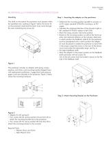
MOUNTING and COMMISSIONING INSTRUCTIONS Mounting Step 1: Mounting the adapter on the positioner The shaft on the bottom the positioner must operate within the specified area. Looking at figure 1 below, the arrow (1) on the positioner shaft (and the lever) must move through the area marked by the arrows (2). • Determine the mounting position (parallel to actuator or at 90° angle, standard 1177D-EP2 mounting is at 90° angle). • Calculate the rotational direction of the actuator (right or left, standard 1177D-EP2 rotation is left CCW). • Move the rotary actuator into home position. • Based on the...
Open the catalog to page 3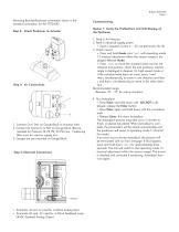
Mounting Bracket/Positioner orientation shown is the standard orientation for the 1177D-EP2 Step 3: Attach Positioner to Actuator Option 1: Using the Pushbuttons and LCD Display on the Positioner 1. Connect Out 1 Port on Gauge Block to Actuator Inlet 2. Connect Air Source to In Port on Gauge Block (Recommended Air Pressure 70-90 PSI, 90 PSI max. Coalescing filter must be used on supply air) 3. Gauges are pre-mounted on Gauge Block Step 5: Electrical Connections • Terminals +11 and -12 used for 4-20mA Analog Input • Terminals +31 and -32 used for 4-20mA Feedback Loop 24VDC Powered Analog Output...
Open the catalog to page 4
Option 2: Using a HART Communicator 1. Feed in Air Pressure 2. Feed in electrical supply power • Feed in setpoint current 4 ... 20 mA (terminals +11 / -12) 3. Connect HART communicator to terminals 11 and 12 coming from the positioner 4. Go online with the communicator. Then go to Settings→ Valve Parameters→ Auto Configuration→ Start Auto Configuration Performing a hard reset In the event a hard reset needs to be made to the positioner, the following must be performed using the pushbuttons: 3. Press Enter and hold down until the countdown ends to activate the save position. Release the Enter...
Open the catalog to page 5All FIVES PILLARD catalogs and technical brochures
 Pillard LM3086 SE
2 Pages
 Pillard Windcross™
2 Pages
 Pillard Nocostop Eco
2 Pages
 Pillard Nocostop Premium™
2 Pages
 Pillard Opastop® GP4000T-EX
2 Pages
 Pillard Opastop® GP4000H-EX
2 Pages
 Pillard Dieselight™
2 Pages
 Pillard Opastop® GP4000H
2 Pages
 Pillard Opastop® GP4000H-C
2 Pages
 Pillard DarkscanFlex™
2 Pages
 Pillard Oxycheck™
2 Pages
 Pillard Packlight™
2 Pages
 Pillard flame scanners
4 Pages
 Pillard Smokecheck™
2 Pages
 Pillard Powerpack™
2 Pages
 Pillard Windcheck™
2 Pages
 Pillard Powerpack™
2 Pages
 OPASTOP GP4000H-EX
2 Pages
 Pillard TK Drain
2 Pages
 INDUCTFLAM® L
2 Pages
 OPAGAZ
2 Pages
 Pillard RotaFlam®
2 Pages
 Pillard PrecaFlam™
2 Pages
 Pillard NovaFlam®
2 Pages
 Blower Silencers
2 Pages
 Series 2300 Turbo Blowers
7 Pages
 SAF – Adjustable Flow Valve
2 Pages
 Limiting Orifi ce Gas Valves
3 Pages
 Double Shutoff Valve
2 Pages
 Oil Shutoff Valves
6 Pages
 Pneumatic Cycle Valve
2 Pages
 Air Cycling Valve
2 Pages
 Wafer Butterfly Valves
4 Pages
 1008A-C / 1010A-C-1
3 Pages
 Adjustable Port Valves
4 Pages
 Butterfl y Valves
4 Pages
 ITAS Ductflame
4 Pages
 ITAS Speedflame
4 Pages
 ITAS Dryflame
4 Pages
 ITAS Intensityflame
4 Pages
 Adjustable Port Valves
2 Pages
 Waste heat recovery
48 Pages
 Pillard Opastop® GP3050ST
2 Pages
 Pillard SmokecheckTM
2 Pages
 Pillard Windcheck™
2 Pages
 Pillard NocostopTM
2 Pages


Archived catalogs
 Pillard Packlight
2 Pages
 Pillard flame scanners
4 Pages
- Gas analyzer
- Management software solution
- Concentration analyzer
- Monitoring analyzer
- Liquids analyzer
- Pressure limiter
- Real-time software
- Solids analyser
- Monitoring software solution
- Industrial software
- Continuous analyzer
- Real-time analyzer
- Oxygen analyzer
- Industrial detector
- Gas pressure limiter
- Calibration analyzer
- Monitoring detector
- Waterproof analyzer
- Temperature analyzer
- RS485 analyzer