- Catalogs
- FISHER REGULATORS
- Y696VR Series Vacuum Regulator
Y696VR Series Vacuum Regulator
1 /4Pages

Y696VR Series Vacuum Regulator
1 /4Pages
Catalog excerpts

Y696VR Series Vacuum Regulator Introduction The Y696VR Series are direct-operated vacuum regulators used where a decrease in vacuum (increase in absolute pressure) must be limited, such as between a tank and vacuum source to control vacuum in the tank. The Type Y696VR has internal pressure registration. The Type Y696VRM has a control line connection port and blocked throat for external pressure registration. Features • Precision Control of Low Pressure Settings— Large diaphragm areas provide more accurate control at low pressure settings. • Installation Adaptability—Four-position vent mounting and 360° adjustability of the union nut connection permit flexibility in vent positioning and installation in awkward positions or limited spaces. • Corrosion Resistance—Constructions are available in a variety of materials for compatibility with corrosive process gases. Principle of Operation A vacuum regulator maintains a constant vacuum at the regulator inlet. A decrease in vacuum (increase in absolute pressure) below the setpoint registers on the diaphragm and opens the disk. This allows the pressure from the higher vacuum source to pass through the regulator and restore the vacuum to its original setting. On the Type Y696VR, the controlled pressure registers directly into the diaphragm casing. The Type Y696VRM has a control line connecting the diaphragm casing to the vacuum being controlled and an O-ring stem seal blocking the throat allowing for registration only through the control line connection. Figure 1. Type Y696VR Vacuum Regulator Installation The versatility of the Y696VR Series devices permits a wide variety of installations. The body may be mounted in any position (360° rotation possible) relative to the spring and diaphragm cases just by loosening the union nut and rotating the diaphragm case. Spring case can be rotated to fit the application required. Any mounting position provides excellent performance. When exposed to the weather, spring case port should be protected by an optional umbrella vent or pointed downward to allow drainage. When indoors, pipe this port outside if used in hazardous gas service. Downstream piping will vary with the installation. To obtain the calculated characteristics, piping should be the same size as the outlet and straight for the fi
Open the catalog to page 1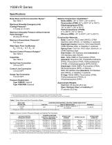
Y696VR Series Specifications Body Sizes and End Connection Styles(1) See Table 1 Maximum Allowable Emergency Inlet (Casing) Pressure(2) ±15 psig (±1,03 bar) Maximum Allowable Pressure without Internal Parts Damage(2) ±8 psig (±0,55 bar) Material Temperature Capabilities(2) Nitrile (NBR): -40° to 180°F (-40° to 82°C) Fluorocarbon (FKM): 40° to 300°F (4° to 149°C) Ethyleneproplyene (EPR): -20° to 200°F (-29° to 93°C) Perfluoroelastomer (FFKM): 0° to 300°F (-18° to 149°C) Silicone (VMQ): -40° to 400°F (-40° to 204°C) Construction Materials Body: Cast iron, WCC steel (NACE), CF8M Stainless steel...
Open the catalog to page 2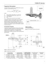
Y696VR Series Capacity Information To determine flow capacities for the Y696VR Series vacuum regulators, use the following formula: VACUUM BEING controlled = flow capacity in scfh (60°F, 14.7 psia) of air = absolute inlet pressure, psia (P1 psig + 14.7) = flow coefficient = 35 = pressure drop across the vacuum breaker If the actual change in control pressure (from the service conditions) is less than the change in vacuum control pressure required to reach wide-open (Table 2), the Cg in the formula must be reduced accordingly. To reduce Cg, multiply Cg (515) by the ratio of the actual change...
Open the catalog to page 3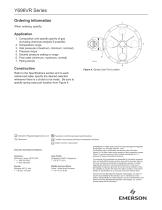
Y696VR Series Ordering Information When ordering, specify: Application 1. Composition and specific gravity of gas (including chemical analysis if possible) 2. Temperature range 3. Inlet pressures (maximum, minimum, nominal) 4. Pressure drops 5. Desired pressure setting or range 6. Flow rates (minimum, maximum, normal) 7. Piping size(s) Figure 4. Spring Case Port Location Refer to the Specifications section and to each referenced table; specify the desired selection whenever there is a choice to be made. Be sure to specify spring case port location from Figure 4. LinkedIn.com/company/emerson-automation-solutions...
Open the catalog to page 4All FISHER REGULATORS catalogs and technical brochures
 ™ Control Valves and Instruments
16 Pages
 Run with higher performing,
16 Pages
 R Series
2 Pages
 LP-Gas Technologies
118 Pages
 Industrial Regulators
2 Pages
 Type 92B Pressure Reducing Valve
16 Pages
 Type 630R Relief Valve
8 Pages
 Fisher™ 585C Piston Actuators
16 Pages
 Type 630 Regulator
16 Pages
 Fisher™ YD and YS Control Valves
24 Pages
 easy-e Cryogenic Valves
12 Pages
 Large ET and ED Valves
20 Pages
 1305 Series Regulators
4 Pages
 H200 Series Relief Valves
4 Pages
 Air Application Map
1 Page
 DeltaV Controller Firewall
11 Pages
 CSI 6500 Overview
12 Pages
 The Criticality of Cooling
5 Pages
 Ovation Security Center
4 Pages
 DeltaV Smart Switches
28 Pages
 Smartprocess™ Heater
5 Pages
 FPSO Industry Solution
2 Pages
 LP-31
LP-3196 Pages
 CS 200 series
2 Pages
 Regulators Mini Catalog
24 Pages
 1301F, 1301G
12 Pages
 MR95 and MR98
2 Pages
 Fisher® D and DA Valves
12 Pages
 Fisher® EZ easy-e Control Valve
40 Pages
 Fisher® YD and YS Control Valves
24 Pages
 Fisher® HPNS Control Valve
36 Pages
 Fisher® HP Series Control Valves
28 Pages
 Fisher® CAV4 Control Valve
28 Pages
 Fisher® 377 Trip Valve
20 Pages
 EZR Pressure Reducing Regulator
36 Pages
 630 Regulator
16 Pages
 627F Pressure Reducing Regulator
12 Pages
 ACE97 Pad-Depad Valve
16 Pages
 310A Pressure Reducing Regulator
16 Pages
 S200 series
32 Pages
 R622 series
8 Pages
 Type HSR Pressure Regulators
20 Pages
 cs200 series
40 Pages
 CS400 Series
60 Pages
 167D Series Switching Valves
8 Pages


Archived catalogs
 Pressure Equivalents
1 Page
 Pipe and Tubing Sizing
1 Page


- SARRALLE valve
- SARRALLE manual valve
- SARRALLE control valve
- SARRALLE stainless steel valve
- SARRALLE ball valve
- SARRALLE pneumatic valve
- Threaded valve
- SARRALLE regulating valve
- Flange valve
- SARRALLE shut-off valve
- SARRALLE electric valve
- ISO valve
- Level limit switch
- Pressure gauge
- SARRALLE pressure regulator
- SARRALLE gas valve
- Valve with handwheel
- Liquid level detector
- SARRALLE pneumatically-operated valve
- SARRALLE level sensor