- Catalogs
- FISHER REGULATORS
- Y610A, Y611A and Y612A Series Vacuum Service Equipment and Relief Valves
Y610A, Y611A and Y612A Series Vacuum Service Equipment and Relief Valves
1 /12Pages

Y610A, Y611A and Y612A Series Vacuum Service Equipment and Relief Valves
1 /12Pages
Catalog excerpts
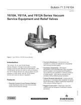
Y610A, Y611A, and Y612A Series Vacuum Service Equipment and Relief Valves Figure 1. Type Y610A or Y610AP Vacuum Breaker Introduction The Y610A, Y611A, and Y612A Series devices (Figures 1 through 4) are used in a wide variety of vacuum and relief service applications. The Y610A Series devices are used as vacuum breakers, the Y611A Series devices are used as either vacuum breakers or relief valves, and the Y612A Series devices are used as vacuum regulators. • Installation Adaptability—360-degree adjustability of the body/diaphragm case connection and four-position vent mounting permit flexibility in vent positioning and installation in awkward positions or limited spaces. Units may be mounted in any orientation without affecting proper operation. • Tamper-Resistant Adjustment—Closing cap and spring case on most types allow installation of sealing wire to discourage or detect unauthorized adjustment of the pressure setting (Figure 2). • Rugged Construction—Diaphragm case and internal parts are designed to withstand vibration and shock. D103115X012 • Precision Control of Low-Pressure Setting— Large diaphragm areas provide more accurate control at low-pressure settings. • Corrosion Resistance—Constructions are available in a variety of materials for compatibility with corrosive process gases.
Open the catalog to page 1
Bulletin 71.3:Y610A Specifications Available Configurations See Table 1 Body Sizes (Inlet x Outlet) and End Connection Style(1) Type Y610A, Y610AP, Y611A, Y611AP, Y612A, or Y612AP: 1-1/2 x 1-1/2, 2 x 2 NPT, or NPS 2 x 2 / DN 50 x 50, CL125 FF, or CL250 RF flanged Pressure Information(2) Type Y610A or Y610AP Vacuum Breaker: See Table 2 Type Y611A or Y611AP Relief Valve: See Table 3 Type Y612A or Y612AP Vacuum Regulator: See Table 4 Port Diameters and Flow Coefficients TYPE NUMBER SEAT RING PORT DIAMETER Cg WITH FULLY OPEN DISK Typical Flow Capacities and Performance Curves Y610A Series Vacuum...
Open the catalog to page 2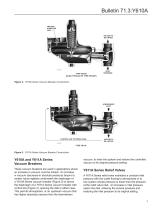
Bulletin 71.3:Y610A TWO WAY STABILIZER VENT VACUUM TO BE LIMITED TYPE Y610A (ALSO TYPICAL OF TYPE Y610AP) INLET PRESSURE Figure 2. Y610A Series Vacuum Breaker Construction ATMOSPHERIC INLET CONTROL LINE TO SPRING CASE Figure 3. Y611A Series Vacuum Breaker Construction Y610A and Y611A Series Vacuum Breakers vacuum, to enter the system and restore the controlled vacuum to its original pressure setting. These vacuum breakers are used in applications where an increase in vacuum must be limited. An increase in vacuum (decrease in absolute pressure) beyond a certain value registers underneath the diaphragm...
Open the catalog to page 3
VACUUM BEING REGULATED HIGHER VACUUM SOURCE TYPE Y612A (ALSO TYPICAL OF TYPE Y612AP) Figure 4. Y612A Series Vacuum Regulator Construction Y612A Series Vacuum Regulators These vacuum regulators (Figure 4) maintain a constant vacuum at the regulator inlet. A decrease in this vacuum (increases in absolute pressure) beyond this value registers underneath the diaphragm and opens the disk. This permits a downstream vacuum of lower absolute pressure than the upstream vacuum to restore the upstream vacuum to its original pressure setting. To determine capacities at outlet or relief set pressure not given...
Open the catalog to page 4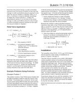
Bulletin 71.3:Y610A Note that if the actual change in outlet (controlled) pressure (from the service condition) is less than the change in outlet (controlled) pressure required to fully open the vacuum breaker or regulator Table 2 or 5, the Cg in formula (1) must be reduced accordingly. To obtain the correct reduced Cg, multiply the Specifications section Cg by the ratio of the actual change in outlet (controlled) pressure to the change in outlet (controlled) pressure required to fully open the vacuum breaker or regulator. Relief Valve Application Q = (P1 + buildup) abs Cg x sin (P1 + buildup)...
Open the catalog to page 5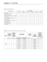
Table 1. Available Configurations TYPE NUMBER Vacuum breaker or relief valve Relief pilot with solid throat Relief pilot with bleed hole in throat for Type 66RR Vacuum regulator 1-1/2 or 2 NPT end connections and spring case with 1 NPT screened vent Internal registration Vacuum breaker External registration with 1/2 NPT downstream control line connection Light diaphragm plate(s) Heavy diaphragm plate(s) O-ring stem seal Table 2. Types Y610A and Y610AP Vacuum Breaker Pressure Information MAXIMUM EMERGENCY OUTLET (CASING) PRESSURE (POSITIVE) TYPE NUMBER MAXIMUM ALLOWABLE INLET (BODY) PRESSURE OUTLET...
Open the catalog to page 6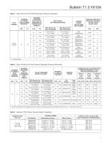
Bulletin 71.3:Y610A Table 3. Types Y611A and Y611AP Relief Valve Pressure Information TYPE NUMBER MAXIMUM ALLOWABLE INLET (CASING) PRESSURE(1) MAXIMUM OPERATING INLET (RELIEF) PRESSURE TO PREVENT PART DAMAGE(1) INLET RELIEF SET PRESSURE RANGE CONTROL SPRING COLOR CODE, PART NUMBER With Spring Case Above Diaphragm With Spring Case Below Diaphragm BUILDUP OVER INLET PRESSURE REQUIRED TO FULLY OPEN RELIEF VALVE Table 4. Types Y612A and Y612AP Vacuum Regulator Pressure Information MAXIMUM ALLOWABLE INLET (CASING) PRESSURE MAXIMUM OPERATING INLET PRESSURE TO PREVENT PART DAMAGE With Spring Case Above...
Open the catalog to page 7
INLET PRESSURE, mbar INLET PRESSURE, psig FLOW RATE, SCFH / Nm3/h OF AIR NPS 1-1/2 OR 2 / DN 40 OR 50 TYPE Y611A WITH 1-3/16-INCH / 30 mm SEAT RING NOTE: SEE CAPACITY INFORMATION SECTION FOR CONVERSION TO EQUIVALENT CAPACITIES OF OTHER GASES AND/OR CUBIC METERS PER HOUR. EACH CURVE REPRESENTS A DIFFERENT CONTROL SPRING AS MARKED AND INITIAL RELIEF SET PRESSURE FOR THAT SPRING AS GIVEN IN TABLE 6. DO NOT BASE YOUR CAPACITY ON A CONTROL SPRING SETTING HIGHER THAN THE MAXIMUM OPERATING INLET (RELIEF) PRESSURE TO PREVENT PART DAMAGE AS GIVEN IN TABLE 3. SPRING 1A630627022 WITH 1-3/16-INCH / 30 mm...
Open the catalog to page 8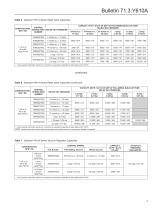
Bulletin 71.3:Y610A Table 6. Selected Y611A Series Relief Valve Capacities CONTROL CONSTRUCTION, SPRING PART RELIEF SET PRESSURE NPS / DN NUMBER 1D892527022 14 inches w.c. / 21 inches w.c. / 35 mbar 52 mbar CAPACITY, SCFH / Nm3/h OF AIR(1) AT FOLLOWING BUILD-UP OVER RELIEF SET PRESSURE 1. See Capacity Information section for conversion to equivalent capacities of other gases and/or Nm3/h. Table 6. Selected Y611A Series Relief Valve Capacities (continued) CAPACITY, SCFH / Nm3/h OF AIR(1) AT FOLLOWING BUILD-UP OVER RELIEF SET PRESSURE CONTROL SPRING PART NUMBER 1D892527022 1. See Capacity...
Open the catalog to page 9All FISHER REGULATORS catalogs and technical brochures
 ™ Control Valves and Instruments
16 Pages
 Run with higher performing,
16 Pages
 R Series
2 Pages
 LP-Gas Technologies
118 Pages
 Industrial Regulators
2 Pages
 Type 92B Pressure Reducing Valve
16 Pages
 Type 630R Relief Valve
8 Pages
 Fisher™ 585C Piston Actuators
16 Pages
 Type 630 Regulator
16 Pages
 Fisher™ YD and YS Control Valves
24 Pages
 easy-e Cryogenic Valves
12 Pages
 Large ET and ED Valves
20 Pages
 1305 Series Regulators
4 Pages
 H200 Series Relief Valves
4 Pages
 Air Application Map
1 Page
 DeltaV Controller Firewall
11 Pages
 CSI 6500 Overview
12 Pages
 The Criticality of Cooling
5 Pages
 Ovation Security Center
4 Pages
 DeltaV Smart Switches
28 Pages
 Smartprocess™ Heater
5 Pages
 FPSO Industry Solution
2 Pages
 LP-31
LP-3196 Pages
 CS 200 series
2 Pages
 Regulators Mini Catalog
24 Pages
 1301F, 1301G
12 Pages
 MR95 and MR98
2 Pages
 Fisher® D and DA Valves
12 Pages
 Fisher® EZ easy-e Control Valve
40 Pages
 Fisher® YD and YS Control Valves
24 Pages
 Fisher® HPNS Control Valve
36 Pages
 Fisher® HP Series Control Valves
28 Pages
 Fisher® CAV4 Control Valve
28 Pages
 Fisher® 377 Trip Valve
20 Pages
 EZR Pressure Reducing Regulator
36 Pages
 630 Regulator
16 Pages
 627F Pressure Reducing Regulator
12 Pages
 ACE97 Pad-Depad Valve
16 Pages
 310A Pressure Reducing Regulator
16 Pages
 S200 series
32 Pages
 R622 series
8 Pages
 Type HSR Pressure Regulators
20 Pages
 cs200 series
40 Pages
 CS400 Series
60 Pages
 167D Series Switching Valves
8 Pages


Archived catalogs
 Pressure Equivalents
1 Page
 Pipe and Tubing Sizing
1 Page


- SARRALLE manual valve
- SARRALLE control valve
- SARRALLE stainless steel valve
- SARRALLE ball valve
- SARRALLE pneumatic valve
- Threaded valve
- SARRALLE regulating valve
- Flange valve
- SARRALLE shut-off valve
- SARRALLE electric valve
- ISO valve
- Level limit switch
- Pressure gauge
- SARRALLE pressure regulator
- SARRALLE gas valve
- Valve with handwheel
- Liquid level detector
- SARRALLE pneumatically-operated valve
- SARRALLE level sensor