Catalog excerpts

Bulletin 71.1:Y600A January 2010 Y600A Series Pressure Reducing Regulators W7095 Figure 1. Type Y600A Pressure Reducing Regulator Introduction Features Y600A Series direct-operated, spring-loaded regulators provide economical pressure-reducing control for a variety of residential, commercial, and industrial applications. • Precision Control at Low-Pressure Settings— The large diaphragm area provides more accurate control at low-pressure settings. The pitot tube of Types Y600A and Y600AR (Figure 2) regulators also creates a dynamic boost that helps provide greater capacity. The large diaphragm area provides more accurate control at low-pressure settings, and the pitot tube of the Type Y600A or Y600AR regulator also creates a dynamic boost that helps provide greater capacity. • Tamper-Resistant Adjustment—The closing cap and spring case (Figure 2) allow the installation of sealing wire to discourage or detect unauthorized adjustment of the pressure setting. • Easy to Maintain—Trim parts can be replaced without removing the regulator body from the pipeline. A two-bolt connection between the body and diaphragm casing simplifies disassembly for maintenance. D102575X012 The Type Y600A features internal registration. The Type Y600AR has internal registration and relief. The Type Y600AM uses external registration with a 1/2 NPT downstream control line connection and an O-ring stem seal. • Easy Conversion Between Types Y600A and Y600AM—The throat seal can be modified to either version. A new lower casing is not needed. www.fisherregulators.com
Open the catalog to page 1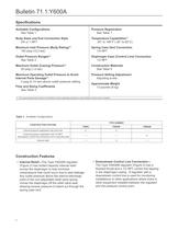
Available Configurations Body Sizes and End Connection Style Maximum Inlet Pressure (Body Rating)111 Maximum Outlet (Casing) Pressure111 Maximum Operating Outlet Pressure to Avoid 2 psig (0,14 bar) above outlet pressure setting Flow and Sizing Coefficients Pressure Registration Spring Case Vent Connection Diaphragm Case (Control Line) Connection Construction Materials Pressure Setting Adjustment Adjusting screw Approximate Weight 1. The pressure/temperature limits in this Bulletin and any applicable standard or code limitation should not be exceeded Table 1. Available Configurations...
Open the catalog to page 2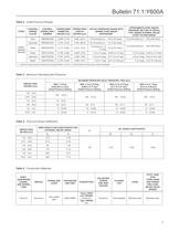
Table 2. Outlet Pressure Ranges Table 3. Maximum Operating Inlet Pressures Table 4. Flow and Sizing Coefficients Table 5. Construction Materials
Open the catalog to page 3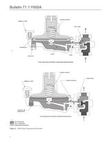
Bulletin 71.1:Y600A control spring umbrella vent pitot tube diaphragm B2622 lever pipe plug stem Type Y600A with internal pressure registration control spring THROAT SEAL O-RING STEM SEAL UMBRELLA VENT CONTROL LINE CONNECTION Type Y600AM with external pressure registration W7325 inlet pressure outlet pressure atmospheric pressure Figure 2. Y600A Series Operational Schematic 4
Open the catalog to page 4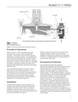
Bulletin 71.1:Y600A relief valve spring valve disk pusher post pipe plug orifice Type Y600AR with internal relief/internal pressure registration B2623 inlet pressure outlet pressure atmospheric pressure Figure 2. Y600A Series Operational Schematic (continued) Principle of Operations Refer to Figure 2. When downstream demand decreases, the pressure under the diaphragm increases. This pressure overcomes the regulator setting (which is set by a spring). Through the action of the pusher post assembly, the valve disk moves closer to the orifice and reduces gas flow. If demand downstream...
Open the catalog to page 5
Capacity Information Tables 6 and 7 give the natural gas regulating capacities ofY600A Series regulators at selected inlet pressures and outlet pressure settings. Flows are in SCFH (60°F and 14.7 psia) of 0.6 specific gravity gas. To determine equivalent capacities for air, propane, butane, or nitrogen, multiply the Table 6 or 7 capacity by the following appropriate conversion factor: 0.775 for nitrogen. For gases of other specific gravities, multiply the given capacity by 0.775, and divide by the square root of the appropriate specific gravity. Then, if capacity is desired in normal cubic...
Open the catalog to page 6
Table 6. Y600A Series Capacities for 3/4 NPT Body Size (continued)
Open the catalog to page 7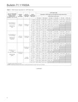
Table 7. Y600A Series Capacities for 1 NPT Body Size
Open the catalog to page 8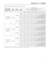
Table 7. Y600A Series Capacities for 1 NPT Body Size (continued)
Open the catalog to page 9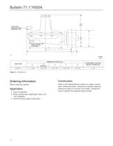
Bulletin 71.1:Y600A 5.56 (141) 1/4 NPT VENT CONNECTION WITH REMOVABLE VENT A A/2 1/2 NPT CONTROL LINE CONNECTION ON TYPE Y600AM D E F G B2604 INCHES (mm) DIMENSION, INCHES (mm) BODY SIZE 3/4 and 1 A D (Diameter) E F G APPROXIMATE SHIPPING WEIGHT, POUNDS (kg) 4 (102) 8.38 (213) 6.25 (159) 10.69 (272) 1.00 (25) 13 (6) Figure 3. Dimensions Ordering Information When ordering, specify: Application 1. Type of regulator 2. Body, spring case, diaphragm case, and trim materials 3. Control spring range in psig (bar) 10 Construction Refer to the Specifications section on page 2 and to...
Open the catalog to page 10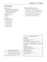
Ordering Guide □ Y600A (internal pressure registration)*** □ Y600AM (external pressure registration)* pressure registration)** Body Size (Select One) Orifice Size (Select One) Outlet Pressure Ranges (Select One) □ 15-inches w.c. to 1.2 psig (37 to 83 mbar), Yellow* □ 2.5 to 4.5 psig (0,17 to 0,31 bar), Light Blue*** Regulators Quick Order Guide Availability of the product being ordered is determined by the component with the longest shipping time for the requested construction. Specification Worksheet Line Size_ Gas Type and Specific Gravity _ Does the Application Require Overpressure...
Open the catalog to page 11
Industrial Regulators Emerson Process Management Middle East and Africa Dubai, United Arab Emirates Emerson Process Management Emerson Process Management Tescom Corporation For further information visit www.fisherregulators.com The Emerson logo is a trademark and service mark of Emerson Electric Co. All other marks are the property of their prospective owners. Fisher is a mark owned by Fisher Controls, Inc., a business of Emerson Process Management The contents of this publication are presented for informational purposes only, and while every effort has been made to ensure their accuracy...
Open the catalog to page 12All FISHER REGULATORS catalogs and technical brochures
-
™ Control Valves and Instruments
16 Pages
-
Run with higher performing,
16 Pages
-
R Series
2 Pages
-
LP-Gas Technologies
118 Pages
-
Industrial Regulators
2 Pages
-
Type 92B Pressure Reducing Valve
16 Pages
-
Type 630R Relief Valve
8 Pages
-
Fisher™ 585C Piston Actuators
16 Pages
-
Type 630 Regulator
16 Pages
-
Fisher™ YD and YS Control Valves
24 Pages
-
easy-e Cryogenic Valves
12 Pages
-
Large ET and ED Valves
20 Pages
-
1305 Series Regulators
4 Pages
-
H200 Series Relief Valves
4 Pages
-
Air Application Map
1 Pages
-
DeltaV Controller Firewall
11 Pages
-
CSI 6500 Overview
12 Pages
-
The Criticality of Cooling
5 Pages
-
Ovation Security Center
4 Pages
-
DeltaV Smart Switches
28 Pages
-
Smartprocess™ Heater
5 Pages
-
FPSO Industry Solution
2 Pages
-
LP-31
96 Pages
-
CS 200 series
2 Pages
-
Regulators Mini Catalog
24 Pages
-
1301F, 1301G
12 Pages
-
MR95 and MR98
2 Pages
-
Fisher® D and DA Valves
12 Pages
-
Fisher® EZ easy-e Control Valve
40 Pages
-
Fisher® YD and YS Control Valves
24 Pages
-
Fisher® HPNS Control Valve
36 Pages
-
Fisher® HP Series Control Valves
28 Pages
-
Fisher® CAV4 Control Valve
28 Pages
-
Fisher® 377 Trip Valve
20 Pages
-
EZR Pressure Reducing Regulator
36 Pages
-
630 Regulator
16 Pages
-
627F Pressure Reducing Regulator
12 Pages
-
ACE97 Pad-Depad Valve
16 Pages
-
310A Pressure Reducing Regulator
16 Pages
-
S200 series
32 Pages
-
R622 series
8 Pages
-
Type HSR Pressure Regulators
20 Pages
-
cs200 series
40 Pages
-
CS400 Series
60 Pages
-
167D Series Switching Valves
8 Pages
Archived catalogs
-
Vapor Pressures of LP-Gas
1 Pages
-
Pipe and Tubing Sizing
1 Pages
-
Average Properties of LP-Gas
1 Pages
-
Pressure Equivalents
1 Pages


