
- Catalogs
- FISHER REGULATORS
- Type Y692 Gas Blanketing Regulator System

Type Y692 Gas Blanketing Regulator System

Type Y692 Gas Blanketing Regulator System
The Type Y692 Gas Blanketing Regulator System is engineered to maintain a protective environment over stored liquids by reducing high-pressure gases such as nitrogen. It ensures a slight positive pressure to prevent contaminants and potential vessel collapse.
- Ease of Inspection and Maintenance: The union nut connection facilitates easy access to internal components without removing the regulator from the line.
- Accuracy of Control: Large diaphragm areas provide precise control, even at low pressures.
- Speed of Response: Direct sensing of downstream pressure allows for a quick response.
- Ease of Installation: No additional connections are required for installation.
The regulator is available in NPS 1-1/2 and 2 / DN 40 and 50 body sizes, with options for internal or external pressure registration and seven outlet pressure ranges.
- Maximum Inlet Pressure: 150 psig / 10.3 bar
- Maximum Outlet Pressure: 15 psig / 1.0 bar
- Temperature Capabilities: Varies with diaphragm material, ranging from -20 to 300°F / -29 to 149°C.
- Construction Materials: Includes cast iron, steel, stainless steel, and various elastomers for different components.
The regulator maintains a low-pressure gas blanket over the liquid in a vessel, adjusting gas flow to maintain desired pressure in response to pressure changes.
Install with the spring case barrel pointed down to achieve the lowest set pressure. Ensure proper flow direction as indicated on the regulator body.
Consider both gas replacement for liquid loss and vapor contraction due to cooling. Use the direct displacement method cautiously and follow API 2000 standards for accurate sizing.
Specify the type of gas, specific gravity, temperature, inlet pressures, flow rates, line size, and vessel size when ordering.
Refer to Table 5 for typical regulating capacities at selected pressures.
Formulas are provided for calculating gas flow capacities, specifically for nitrogen. Adjust for specific gravities by multiplying the nitrogen capacity by 0.985 and dividing by the square root of the specific gravity of the required gas. For capacities in normal cubic meters per hour at 0°C and 1.01325 bar, multiply SCFH by 0.0268. The formula for wide-open flow capacities for relief sizing involves variables such as gas sizing coefficient (Cg), specific gravity (G), and inlet pressure (P1abs).
Table 5 details the blanketing regulating capacities for nitrogen with a specific gravity of 0.97, across various body sizes, outlet pressure ranges, and orifice sizes, highlighting areas where droop or maximum operating inlet pressure is exceeded.
Table 6 lists orifice sizes and coefficients for relief valve sizing, including wide-open Cv and Cg values for different body sizes and orifice dimensions.
The guide outlines options for selecting orifice size, outlet pressure range, pressure registration, diaphragm protector, CRN, PED conformity, replacement parts kit, body size, material, and end connection style. It also specifies spring case, diaphragm case, trim, diaphragm, and disk materials.
Contact details for Emerson Process Management Regulator Technologies, Inc. are provided for various regions, including the USA, Asia-Pacific, Europe, and the Middle East.
The document includes a tank blanketing specification worksheet for application specifications, pressure requirements, accuracy requirements, and other specifications.
Catalog excerpts

Type Y692 Gas Blanketing Regulator System Figure 1. Type Y692 Low-Pressure Gas Blanketing Regulator An Accu-Pressure™ Gas Blanketing Regulator System reduces a high-pressure gas, such as Nitrogen, to maintain a protective environment above any liquid stored in a tank or vessel when the liquid is being pumped out. Also when the vessel is suddenly cooled, causing vapors inside the vessel to contract, the regulator system replaces the volume of contracting vapors with a volume of blanketing gas to prevent the internal vessel pressure from decreasing. In both cases, a slight positive vessel pressure prevents outside air, moisture and other contaminants from entering the vessel and the possible collapse of the vessel walls. The Type Y692 (Figure 1) is a direct-operated regulator used for accurate pressure control on very low-pressure blanketing systems. Downstream pressure is sensed through a pitot tube installed in the lower casing of the regulator for units with internal pressure registration or through a downstream control line for units with external pressure registration. • Ease of Inspection and Maintenance—The union nut connection between the body and actuator permits access to the disk and orifice by only removing the diaphragm casing assembly without removing the body from the line. • Accuracy of Control—Large diaphragm areas provide more precise control even at low-pressure settings and the pitot tube also creates a dynamic boost that helps provide greater capacity. • Speed of Response—The downstream pressure is sensed directly by the diaphragm through the pitot tube providing quick response. • Ease of Installation—The Type Y692 is easy to install in the pipeline because no additional Process Management
Open the catalog to page 1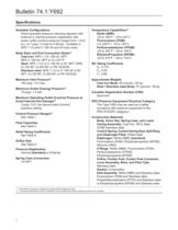
Available Configurations Direct-operated pressure reducing regulator with external or internal pressure registration with seven outlet (control) pressure ranges from 1-inch w.c. to 7 psig / 2 mbar to 0.48 bar. Available in Body Sizes and End Connection Styles'1' Maximum Outlet (Casing) Pressure'2' Maximum Operating Outlet (Control) Pressure to Avoid Internal Part Damage'2' 3 psig / 0.21 bar above outlet (control) pressure setting Flow Capacities Relief Sizing Coefficients Orifice Size Pressure Registration Internal (standard) or External Spring Case Connection Perfluoroelastomer (FFKM): EthylenePropylene...
Open the catalog to page 2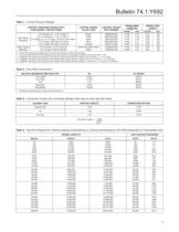
Table 1. Control Pressure Ranges Table 2. Flow Rate Conversion'1' Table 3. Conversion Factors (for converting Nitrogen flow rates to other gas flow rates) Table 4. Gas Flow Required for Thermal Heating (Outbreathing) or Cooling (Inbreathing) per API 2000 (Interpolate for Intermediate size)
Open the catalog to page 3
Bulletin 74.1:Y692 Type Y692 Type Y692 VENT VALVE BLOCK VALVE SUPPLY PRESSURE VENT VALVE VENT POINTED DOWNWARD BLOCK VALVE T GAS BLANKETING PRESSURE July 2007 Type Y692 INLET PRESSURE OUTLET PRESSURE ATMOSPHERIC PRESSURE LIQUID TYPE Y692 WITH INTERNAL REGISTRATION Type Y692 VENT VALVE BLOCK VALVE INLET PRESSURE CONTROL PRESSURE (OUTLET PRESSURE) SUPPLY PRESSURE ATMOSPHERIC PRESSURE VENT VALVE VENT POINTED DOWNWARD BLOCK VALVE GAS BLANKETING PRESSURE LIQUID TYPE Y692 WITH EXTERNAL REGISTRATION A6340 INLET PRESSURE CONTROL PRESSURE (OUTLET PRESSURE) ATMOSPHERIC PRESSURE INLET PRESSURE Figure OUTLET...
Open the catalog to page 4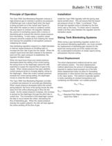
Bulletin 74.1:Y692 Principle of Operation Installation The Type Y692 Gas Blanketing Regulator reduces a high-pressure gas to maintain a positive low-pressure of blanket gas over a stored liquid when the liquid is being pumped out of the vessel (see Figure 2). Also when the vessel (or tank) is suddenly cooled, causing vapors to contract, the regulator replaces the volume of contracting vapors with a volume of blanketing gas to prevent the internal vessel pressure from decreasing. In both cases, a positive vessel pressure prevents outside air from entering the vessel and reduces the possibility...
Open the catalog to page 5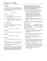
Bulletin 74.1:Y692 API 2000 The American Petroleum Institute Standard 2000 (API 2000) sizing method accounts for liquid pump-out as well as contraction of tank vapors due to cooling. When using API methods: Qtotal = Qpump + Qthermal where, Qtotal = Required Flow Rate Qpump = equired Flow Rate to replace pumped out R liquid from Table 1 Qthermal = equired Flow Rate due to thermal cooling. R See Thermal Equations 1 to 4 below or Table 2. Thermal Equations For tanks up to 840,000 gallons / 3179 m3 capacity, use one of the following equations: Equation 1: Qthermal [SCFH Air] = Vtank x 0.0238 Equation...
Open the catalog to page 6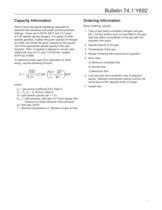
Bulletin 74.1:Y692 Capacity Information Ordering Information Table 5 gives the typical regulating capacities at selected inlet pressures and outlet (control) pressure settings. Flows are in SCFH (60°F and 14.7 psia) of 0.97 specific gravity nitrogen. For gases of other specific gravities, multiply the given capacity of nitrogen by 0.985, and divide the given capacity by the square root of the appropriate specific gravity of the gas required. Then, if capacity is desired in normal cubic meters per hour at 0°C and 1.01325 bar, multiply SCFH by 0.0268. When ordering, specify: To determine wide-open...
Open the catalog to page 7
Table 5. Blanketing Regulating Capacities in SCFH / Nnf/h of 0.97 Specific Gravity Nitrogen ORIFICE SIZE, INCHES / mm 1. Spring ranges based on regulator installation with the spring case pointed down. I I - Light shaded areas show where indicated droop would be exceeded regardless of capacity. I I - Dark shaded areas show where maximum operating inlet pressure for a given orifice size is exceeded.
Open the catalog to page 8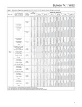
Table 5. Blanketing Regulating Capacities in SCFH / Nnf/h of 0.97 Specific Gravity Nitrogen (continued) 1. Spring ranges based on regulator installation with the spring case pointed down. I I - Light shaded areas show where indicated droop would be exceeded regardless of capacity. I I - Dark shaded areas show where maximum operating inlet pressure for a given orifice size is exceeded.
Open the catalog to page 9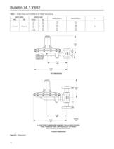
Table 6. Orifice Sizes and Coefficients for Relief Valve Sizing CONTROL LINE A - CAST IRON FLANGES ARE 10-INCHES / 254 mm FACE-TO-FACE; STEEL, STAINLESS STEEL, AND HASTELLOY8 C FLANGES FLANGED DIMENSIONS
Open the catalog to page 10All FISHER REGULATORS catalogs and technical brochures
 Fisher™ 8590 High-Performance
16 Pages
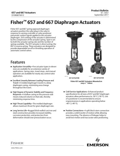 bulletin-fisher-657-and-667
16 Pages
Archived catalogs
 167D Series Switching Valves
8 Pages
 CS400 Series
60 Pages
 cs200 series
40 Pages
 Type HSR Pressure Regulators
20 Pages
 R622 series
8 Pages
 S200 series
32 Pages
 310A Pressure Reducing Regulator
16 Pages
 ACE97 Pad-Depad Valve
16 Pages
 627F Pressure Reducing Regulator
12 Pages
 630 Regulator
16 Pages
 EZR Pressure Reducing Regulator
36 Pages
 Fisher® 377 Trip Valve
20 Pages
 Fisher® CAV4 Control Valve
28 Pages
 Fisher® HP Series Control Valves
28 Pages
 Fisher® HPNS Control Valve
36 Pages
 Fisher® YD and YS Control Valves
24 Pages
 Fisher® EZ easy-e Control Valve
40 Pages
 Fisher® D and DA Valves
12 Pages
 MR95 and MR98
2 Pages
 1301F, 1301G
12 Pages
 Regulators Mini Catalog
24 Pages
 CS 200 series
2 Pages
 LP-31
LP-3196 Pages
 FPSO Industry Solution
2 Pages
 Smartprocess™ Heater
5 Pages
 DeltaV Smart Switches
28 Pages
 Ovation Security Center
4 Pages
 The Criticality of Cooling
5 Pages
 CSI 6500 Overview
12 Pages
 DeltaV Controller Firewall
11 Pages
 Air Application Map
1 Page
 H200 Series Relief Valves
4 Pages
 1305 Series Regulators
4 Pages
 Large ET and ED Valves
20 Pages
 easy-e Cryogenic Valves
12 Pages
 Fisher™ YD and YS Control Valves
24 Pages
 Type 630 Regulator
16 Pages
 Fisher™ 585C Piston Actuators
16 Pages
 Type 630R Relief Valve
8 Pages
 Type 92B Pressure Reducing Valve
16 Pages
 Industrial Regulators
2 Pages
 LP-Gas Technologies
118 Pages
 R Series
2 Pages
 Run with higher performing,
16 Pages
 ™ Control Valves and Instruments
16 Pages
 Pressure Equivalents
1 Page
 Pipe and Tubing Sizing
1 Page


- Manual valve
- FISHER control valve
- FISHER stainless steel valve
- Ball valve
- FISHER pneumatic valve
- Threaded valve
- Regulating valve
- Flange valve
- On/off valve
- Electric valve
- ISO valve
- Pressure gauge
- Level limit switch
- FISHER pressure regulator
- Gas valve
- Valve with handwheel
- FISHER pneumatically-operated valve
- Liquid level detector
- Butterfly valve