Catalog excerpts
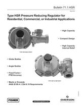
Bulletin 71.1:HSR May 2010 Type HSR Pressure Reducing Regulator for Residential, Commercial, or Industrial Applications • High Capacity • Compact Design • High Capacity Internal Relief Type HSR Angle Body • Globe Bodies • Angle Bodies • Fixed Factor / PFM Accuracy Type HSR GLOBE BODY D103087X012 • Meets or Exceeds ANSI B109.4 / CGA 6.18 Requirements www.fisherregulators.com
Open the catalog to page 1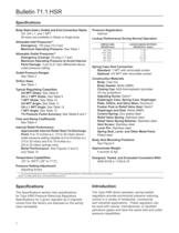
Body Sizes (Inlet x Outlet) and End Connection Styles All sizes are available in Globe or Angle body. Maximum Operating Pressure: See Table 1 Emergency (Casing): 25 psig (1,7 bar) Maximum Operating Pressure to Avoid Internal Parts Damage: 3 psi (0,21 bar) differential above outlet pressure setting Outlet Pressure Ranges Orifice Sizes Typical Regulating Capacities 1% Pressure Factor Accuracy: See Tables 6 and 7 Flow and Sizing Coefficients Internal Relief Performance Approximate Internal Relief Start-To-Discharge Point: 6 to 12-inches w.c. (15 to 30 mbar) above outlet pressure setting...
Open the catalog to page 2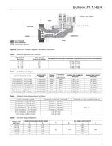
Table 1. Maximum Operating Inlet Pressure Table 2. Outlet Pressure Ranges Table 3. Standard Outlet Pressures and Set Flows Table 4. Flow and Sizing Coefficients
Open the catalog to page 3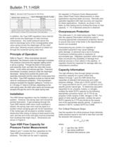
Table 5. Standard Inlet Pressures for Set Flows In addition, the Type HSR regulators have internal relief across the diaphragm to help minimize overpressure. Any outlet pressure above the start-to-discharge point of the nonadjustable relief valve spring moves the diaphragm off the relief valve seat, allowing excess pressure to bleed out through the screened spring case vent. Refer to Figure 2. When downstream demand decreases, the pressure under the diaphragm increases. This pressure overcomes the regulator setting (which is set by a spring). Through the action of the pusher post assembly,...
Open the catalog to page 4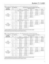
Table 6. Typical HSR Regulating Capacities for a 3/4 NPT Outlet Body Size with 1% Pressure Factor Accuracy Table 7. Typical HSR Regulating Capacities for a 1 NPT Outlet Body Size with 1% Pressure Factor Accuracy
Open the catalog to page 5
Table 8. 3/4 NPT Globe Body Capacities
Open the catalog to page 6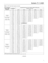
Table 8. 3/4 NPT Globe Body Capacities (continued)
Open the catalog to page 7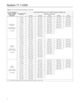
Table 8. 3/4 NPT Globe Body Capacities (continued)
Open the catalog to page 8
Table 9. 3/4 x 1 NPT Globe Body Capacities For Non-Critical Pressure Drops For pressure drops lower than critical (absolute outlet pressure greater than one-half of absolute inlet pressure), use the following formula: Q = gas flow rate, SCFH T = absolute temperature of gas at inlet, "Rankine P1 = absolute inlet pressure, psia AP = pressure drop across the regulator, psi Then, if capacity is desired in normal cubic meters per hour at 0°C and 1,01325 bar, multiply SCFH by 0.0268. Ordering Information Carefully review each specification and complete the Ordering Guide on page 20. Send the...
Open the catalog to page 9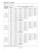
Table 10. 1 NPT Globe Body Capacities
Open the catalog to page 10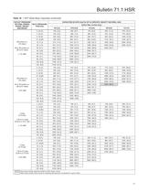
Table 10. 1 NPT Globe Body Capacities (continued)
Open the catalog to page 11
Table 11. 3/4 NPT Angle Body Capacities
Open the catalog to page 12
Table 11. 3/4 NPTAngle Body Capacities (continued)
Open the catalog to page 13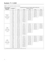
Table 11. 3/4 NPTAngle Body Capacities (continued)
Open the catalog to page 14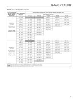
Table 12. 3/4 x 1 NPT Angle Body Capacities
Open the catalog to page 15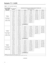
Table 13. 1 NPT Angle Body Capacities
Open the catalog to page 16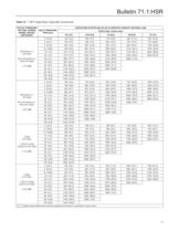
Table 13. 1 NPTAngle Body Capacities (continued)
Open the catalog to page 17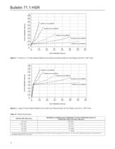
INLET PRESSURE, PSIG (bar) Figure 3. 7-inches w.c. (17 mbar) Setpoint Relief Curves (with Lever Disconnected, No Vent Piping, and 3/4 or 1 NPT Vent) INLET PRESSURE, PSIG (bar) Figure 4. 2 psig (0,14 bar) Setpoint Relief Curves (with Lever Disconnected, No Vent Piping, and 3/4 or 1 NPT Vent) Table 14. Relief Performance
Open the catalog to page 18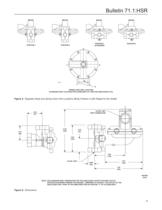
Bulletin 71.1:HSR POSITION 1 POSITION 3 (STANDARD) POSITION 2 POSITION 4 C F D B2504 E SPRING CASE VENT LOCATION (STANDARD VENT LOCATION FOR GLOBE BODY IS F AND FOR ANGLE BODY IS E) Figure 5. Regulator Body and Spring Case Vent Locations (Body Position is with Regard to the Outlet) 3/4 or 1 NPT VENT CONNECTION 2.25 (57) 2.18 (55) 6.39 (162) 2.02 (51) 4.04 (103) 4.58 (116) 3/4 or 1 NPT 5.61 (142) 0.995 (25) 7.20 (183) INCHES (mm) Note: The standard body orientation for the angle body is with the body outlet Rotated 90 degrees toward the reader. Compared to figure 5, the outlet of the...
Open the catalog to page 19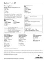
Ordering Guide Body Type, Size and End Connection Style (Select One) Outlet Pressure Range (Select One) □ 1.25 to 2.2 psig (0,09 to 0,15 bar), Light Blue*** Body Orientation (Select One) Globe Angle □ Position 3 (standard)*** □ Position 3 (standard) Vent Size (Select One) Orifice Size (Select One) Vent Orientation (Select One) Specification Worksheet Line Size_ Fluid Type_ Specific Gravity. Does the Application Require Overpressure Protection? Maximum Inlet Pressure. Minimum Inlet Pressure. Differential Pressure_ Maximum Flow_ Accuracy Requirements: Less Than or Equal To: Construction...
Open the catalog to page 20All FISHER REGULATORS catalogs and technical brochures
-
™ Control Valves and Instruments
16 Pages
-
Run with higher performing,
16 Pages
-
R Series
2 Pages
-
LP-Gas Technologies
118 Pages
-
Industrial Regulators
2 Pages
-
Type 92B Pressure Reducing Valve
16 Pages
-
Type 630R Relief Valve
8 Pages
-
Fisher™ 585C Piston Actuators
16 Pages
-
Type 630 Regulator
16 Pages
-
Fisher™ YD and YS Control Valves
24 Pages
-
easy-e Cryogenic Valves
12 Pages
-
Large ET and ED Valves
20 Pages
-
1305 Series Regulators
4 Pages
-
H200 Series Relief Valves
4 Pages
-
Air Application Map
1 Pages
-
DeltaV Controller Firewall
11 Pages
-
CSI 6500 Overview
12 Pages
-
The Criticality of Cooling
5 Pages
-
Ovation Security Center
4 Pages
-
DeltaV Smart Switches
28 Pages
-
Smartprocess™ Heater
5 Pages
-
FPSO Industry Solution
2 Pages
-
LP-31
96 Pages
-
CS 200 series
2 Pages
-
Regulators Mini Catalog
24 Pages
-
1301F, 1301G
12 Pages
-
MR95 and MR98
2 Pages
-
Fisher® D and DA Valves
12 Pages
-
Fisher® EZ easy-e Control Valve
40 Pages
-
Fisher® YD and YS Control Valves
24 Pages
-
Fisher® HPNS Control Valve
36 Pages
-
Fisher® HP Series Control Valves
28 Pages
-
Fisher® CAV4 Control Valve
28 Pages
-
Fisher® 377 Trip Valve
20 Pages
-
EZR Pressure Reducing Regulator
36 Pages
-
630 Regulator
16 Pages
-
627F Pressure Reducing Regulator
12 Pages
-
ACE97 Pad-Depad Valve
16 Pages
-
310A Pressure Reducing Regulator
16 Pages
-
S200 series
32 Pages
-
R622 series
8 Pages
-
cs200 series
40 Pages
-
CS400 Series
60 Pages
-
167D Series Switching Valves
8 Pages
Archived catalogs
-
Vapor Pressures of LP-Gas
1 Pages
-
Pipe and Tubing Sizing
1 Pages
-
Average Properties of LP-Gas
1 Pages
-
Pressure Equivalents
1 Pages


