- Catalogs
- FISHER REGULATORS
- Type 310A-32A Pressure Reducing Regulator
Type 310A-32A Pressure Reducing Regulator
1 /16Pages

Type 310A-32A Pressure Reducing Regulator
1 /16Pages
Catalog excerpts

Type 310A-32A Pressure Reducing Regulator Figure 1. Type 310A Regulator with Type 32A Pilot Introduction The Type 310A pilot-operated high-pressure regulator (Figure 1) is used where high capacity and accurate control are essential. This regulator includes one Type 32A pilot assembly mounted on the main valve for pressure reducing or wide-open monitoring applications or two Type 32A pilots mounted on the main valve for working monitor applications. High Capacity—Straight-through flow passage allows exceptionally high capacities and stable operation. Fast Speed of Response—Designed to meet stringent speed of response requirements for turbine startup and fuel gas applications. Accurate Control—Molded pilot diaphragms provide a narrow proportional band and registration of outlet pressure on the main diaphragm allows excellent control sensitivity. Tight Shutoff—Throttling-sleeve design with Polytetrafluoroethylene (PTFE) seat in the body ensures positive shutoff. Reduced Relief Requirements—Optional restricted trim helps reduce relief valve size requirements; the regulator is easily converted to full capacity by changing the trim, if flow conditions increase. Minimum Installation Space Required—Since main valve design incorporates actuator spring, less installation space is needed for the Type 310A than for other regulators of com
Open the catalog to page 1
Type 310A Specifications This section lists the specifications for the Type 310A regulators. Factory specification are stamped on the nameplate fastened on the regulator at the factory. Available Configurations Type 310A-32A: Type 310A main valve with one Type 32A pilot for standard pressure-reducing and wide-open monitoring applications Type 310A-32A-32A: Type 310A main valve with two Type 32A pilots for working monitor applications Body Sizes and End Connection Styles 1 in. body with NPT ends; and 1, 2, 3, 4 or 4 x 6 in. / DN 25, 50, 80, 100 and 100 x 150 body with CL300 RF or CL600 RF flanged...
Open the catalog to page 2
Type 310A PILOT DIAPHRAGM PLATE YOKE ASSEMBLY BLEED VALVE FIXED RESTRICTION BOTTOM DIAPHRAGM PILOT CONTROL SPRING RELAY SEAT MAIN VALVE DIAPHRAGM THROTTLING SLEEVE INLET PRESSURE OUTLET PRESSURE MAIN VALVE SPRING ATMOSPHERIC PRESSURE LOADING PRESSURE STATIONARY VALVE PLUG PILOT SUPPLY PRESSURE Figure 2. Type 310A-32A Regulator Operational Schematic Principle of Operation Single-Pilot Regulator (Figure 2) The regulator inlet pressure enters the pilot through the external pilot supply line and is utilized as the supply pressure for the pilot. The setting of the pilot control spring determines the...
Open the catalog to page 3
Type 310A The top diaphragm in the pilot acts as a sealing member for the loading chamber and as a balancing member to the bottom diaphragm. The two diaphragms are connected by a yoke. Pressure change to the center chamber has little effect on the positioning of the valve disk. Wide-Open Monitors (Figure 3) Monitoring regulators serve as overpressure protection devices to limit system pressure in the event of failure of working regulators feeding the system. The control line of a wide-open monitoring regulator may be connected downstream of the working regulator, so that during normal operation...
Open the catalog to page 4
Type 310A WORKING PILOT MONITORING PILOT INLET PRESSURE OUTLET PRESSURE ATMOSPHERIC PRESSURE LOADING PRESSURE INTERMEDIATE PRESSURE PILOT SUPPLY PRESSURE Figure 4. Type 310A-32A-32A Working Monitor Regulator Operational Schematic Table 1. Outlet Pressure Ranges OUTLET PRESSURE RANGE psig PROPORTIONAL BAND psig SPRING COLOR SPRING PART NUMBER 1. Available with Nitrile (NBR) pilot diaphragm only. Table 2. Recommended Minimum Differential Between Monitoring Pilot Setting and Distribution Pressure OUTLET PRESSURE RANGE psig SPRING COLOR SPRING PART NUMBER MINIMUM PRESSURE AT WHICH MONITORING PILOT...
Open the catalog to page 5
Type 310A LOADING TUBING HAND VALVE 1/4 IN. NPT PILOT SUPPLY CONNECTION VENT VALVE LOCATE 6 TO 10 PIPE DIAMETERS FROM VALVE OUTLET VENT VALVE BLOCK VALVE HAND VALVE BLOCK VALVE ALTERNATE DOWNSTREAM CONTROL LINE TAP 1/2 IN. / 13 mm DOWNSTREAM CONTROL LINE BYPASS VALVE VENT VALVE Figure 5. Typical Pressure Reducing Installation Capacity Information Note Type 310A regulator flow capacities are laboratory verified; therefore, they may be sized for 100% flow using capacities as shown in Tables 8, 9, 10, 11 and 12. It is not necessary to reduce published capacities. Tables 8, 9, 10, 11 and 12 show...
Open the catalog to page 6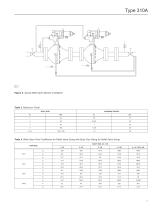
Figure 6. Typical Wide-Open Monitor Installation Table 3. Maximum Travel BODY SIZE MAXIMUM TRAVEL Table 4. Wide-Open Flow Coefficients for Relief Valve Sizing with Body Size Piping for Relief Valve Sizing BODY SIZE, IN. / DN TRIM SIZE
Open the catalog to page 7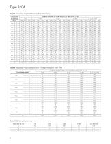
Type 310A Table 5. Regulating Flow Coefficients for Body Size Piping COEFFICIENT AT PERCENT OF MAXIMUM TRAVEL TRIM SIZE (PERCENT OF FLOW CAPACITY) BY BODY SIZE, IN. / DN 1 / 25 Table 6. Regulating Flow Coefficients for 2:1 Swaged Piping and 100% Trim TRIM SIZE (PERCENT OF FLOW CAPACITY) BY BODY SIZE, IN. / DN COEFFICIENT AT PERCENT OF MAXIMUM TRAVEL Table 7. IEC Sizing Coefficients BODY SIZE, IN. / DN
Open the catalog to page 8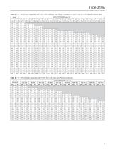
Type 310A Table 8. 1 In. / DN 25 Body Capacities with 100% Trim and Body Size Piping (Thousands of SCFH / Nm3/h) of 0.6 Specific Gravity Gas) INLET PRESSURE OUTLET PRESSURE, psig / bar 25 / 1.7 Table 8. 1 In. / DN 25 Body Capacities with 100% Trim and Body Size Piping (continued) INLET PRESSURE OUTLET PRESSURE, psig / bar 325 / 22.4
Open the catalog to page 9
Type 310A Table 9. 2 In. / DN 50 Body Capacities with 100% Trim and Body Size Piping (Thousands of SCFH / Nm3/h) of 0.6 Specific Gravity Gas) INLET PRESSURE OUTLET PRESSURE, psig / bar 25 / 1.7 Table 9. 2 In. / DN 50 Body Capacities with 100% Trim and Body Size Piping (continued) INLET PRESSURE OUTLET PRESSURE, psig / bar 325 / 22.4
Open the catalog to page 10
Type 310A Table 10. 3 In. / DN 80 Body Capacities with 100% Trim and Body Size Piping (Thousands of SCFH / Nm3/h) of 0.6 Specific Gravity Gas) INLET PRESSURE OUTLET PRESSURE, psig / bar 25 / 1.7 Table 10. 3 In. / DN 80 Body Capacities with 100% Trim and Body Size Piping (continued) INLET PRESSURE OUTLET PRESSURE, psig / bar 325 / 22.4
Open the catalog to page 11All FISHER REGULATORS catalogs and technical brochures
 ™ Control Valves and Instruments
16 Pages
 Run with higher performing,
16 Pages
 R Series
2 Pages
 LP-Gas Technologies
118 Pages
 Industrial Regulators
2 Pages
 Type 92B Pressure Reducing Valve
16 Pages
 Type 630R Relief Valve
8 Pages
 Fisher™ 585C Piston Actuators
16 Pages
 Type 630 Regulator
16 Pages
 Fisher™ YD and YS Control Valves
24 Pages
 easy-e Cryogenic Valves
12 Pages
 Large ET and ED Valves
20 Pages
 1305 Series Regulators
4 Pages
 H200 Series Relief Valves
4 Pages
 Air Application Map
1 Page
 DeltaV Controller Firewall
11 Pages
 CSI 6500 Overview
12 Pages
 The Criticality of Cooling
5 Pages
 Ovation Security Center
4 Pages
 DeltaV Smart Switches
28 Pages
 Smartprocess™ Heater
5 Pages
 FPSO Industry Solution
2 Pages
 LP-31
LP-3196 Pages
 CS 200 series
2 Pages
 Regulators Mini Catalog
24 Pages
 1301F, 1301G
12 Pages
 MR95 and MR98
2 Pages
 Fisher® D and DA Valves
12 Pages
 Fisher® EZ easy-e Control Valve
40 Pages
 Fisher® YD and YS Control Valves
24 Pages
 Fisher® HPNS Control Valve
36 Pages
 Fisher® HP Series Control Valves
28 Pages
 Fisher® CAV4 Control Valve
28 Pages
 Fisher® 377 Trip Valve
20 Pages
 EZR Pressure Reducing Regulator
36 Pages
 630 Regulator
16 Pages
 627F Pressure Reducing Regulator
12 Pages
 ACE97 Pad-Depad Valve
16 Pages
 310A Pressure Reducing Regulator
16 Pages
 S200 series
32 Pages
 R622 series
8 Pages
 Type HSR Pressure Regulators
20 Pages
 cs200 series
40 Pages
 CS400 Series
60 Pages
 167D Series Switching Valves
8 Pages


Archived catalogs
 Pressure Equivalents
1 Page
 Pipe and Tubing Sizing
1 Page


- SARRALLE manual valve
- SARRALLE control valve
- SARRALLE stainless steel valve
- SARRALLE ball valve
- SARRALLE pneumatic valve
- Threaded valve
- SARRALLE regulating valve
- Flange valve
- SARRALLE shut-off valve
- SARRALLE electric valve
- ISO valve
- Level limit switch
- Pressure gauge
- SARRALLE gas valve
- Valve with handwheel
- Liquid level detector
- SARRALLE pneumatically-operated valve
- SARRALLE level sensor