- Catalogs
- FISHER REGULATORS
- T205B Balanced Tank Blanketing Regulator
T205B Balanced Tank Blanketing Regulator
1 /24Pages

T205B Balanced Tank Blanketing Regulator
1 /24Pages
Catalog excerpts

Type T205B Balanced Tank Blanketing Regulator Figure 1. Type T205B Balanced Tank Blanketing Regulator • Fully Balanced Plug Design • Large Diaphragm • Low-Pressure Setting and Fast Speed of Response • Accurate Control and Small Lockup Pressure • Sour Gas Service Capability
Open the catalog to page 1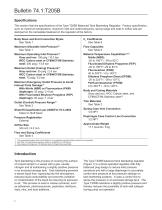
Bulletin 74.1:T205B Specifications This section lists the specifications of the Type T205B Balanced Tank Blanketing Regulator. Factory specification, such as maximum temperature, maximum inlet and outlet pressures, spring range and seat or orifice size are stamped on the nameplate fastened on the regulator at the factory. Body Sizes and End Connection Styles See Table 1 Maximum Allowable Inlet Pressure(1) See Table 1 Flow Capacities See Table 9 Maximum Operating Inlet Pressure(1) Gray cast iron: 150 psig / 10.3 bar WCC Carbon steel or CF8M/CF3M Stainless steel: 200 psig / 13.8 bar Material Temperature...
Open the catalog to page 2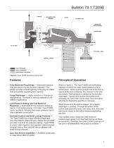
Bulletin 74.1:T205B BALANCED TRIM ASSEMBLY PUSHER POST INLET PRESSURE OUTLET PRESSURE ATMOSPHERIC PRESSURE PRESSURE REGISTRATION VALVE DISK CONTROL SPRING INLET PRESSURE OUTLET PRESSURE ATMOSPHERIC PRESSURE LOADING PRESSURE Figure 2. Type T205B Operational Schematic Type T205B Tank Blanketing Regulator Fully Balanced Plug Design — Eliminates setpoint changes caused by varying inlet pressure. This design provides smooth opening of the plug for stable flow and greater regulating flow capacity. Large Diaphragm — Highly sensitive to changes in tank pressure. Available in various materials to suit...
Open the catalog to page 3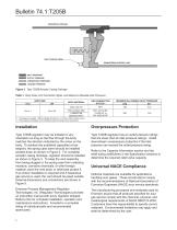
Bulletin 74.1:T205B HORIZONTAL PIPELINE VENT POINTED DOWN DOWNSTREAM CONTROL LINE INLET PRESSURE OUTLET PRESSURE ATMOSPHERIC PRESSURE LOADING PRESSURE Figure 3. Type T205B Actuator Casing Drainage Table 1. Body Sizes, End Connection Styles, and Maximum Allowable Inlet Pressures Inch BODY SIZE BODY MATERIAL MAXIMUM ALLOWABLE INLET PRESSURE psig bar Gray cast iron 3/4 or 1 WCC Carbon steel CF8M/CF3M Stainless steel(2) 1. All flanges are welded. Weld-on flange dimension is 14 inches / 356 mm face-to-face. 2. Pipe nipples and flanges are 316 Stainless steel for flanged body assemblies. Overpressure...
Open the catalog to page 4
Bulletin 74.1:T205B Table 2. Outlet (Control) Pressure Ranges and Spring Information OUTLET (CONTROL) PRESSURE RANGE Inches w.c. SPRING WIRE DIAMETER SPRING COLOR SPRING FREE LENGTH Orange Red Unpainted Yellow Green Light Blue Black 1. Do not use Fluorocarbon (FKM) diaphragm with this spring at diaphragm temperatures lower than 60°F / 16°C. 2. To achieve the published outlet pressure range the spring case must be installed pointing down. Table 3. Available Construction and Trim Materials AVAILABLE CONSTRUCTION MATERIALS Body and Casing Guide Insert Diaphragm Head AVAILABLE TRIM OPTIONS Lever...
Open the catalog to page 5
Table 6. Flow Rate Required due to Thermal Cooling Sizing Blanketing Systems When sizing a gas blanketing regulator system for a low-pressure blanketing application, consider the replacement of blanketing gas required for the liquid loss during pump out of the vessel plus the condensation/contraction of vessel vapors during atmospheric thermal cooling. Using the established procedures from American Petroleum Institute Standard 2000 (API 2000), determine the flow rate of ^total ^pump ^thermal Qtotal: Required Flow Rate. Qpump: Required Flow Rate to replace pumped Qtnermal: Required Flow Rate due...
Open the catalog to page 6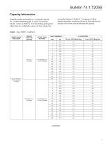
Bulletin 74.1:T205B Capacity Information Capacity tables are based on 1.0 specific gravity air. If other blanketing gas is used, convert the tabular values as follows. For blanketing (pad) gases other than air, multiply the given air flow rate by the correction factors in Table 6. For gases of other specific gravities, divide the given air flow rate by the square root of the appropriate specific gravity. Table 8. Type T205B Cv Coefficient SPRING RANGE AND COLOR OUTLET PRESSURE SETTING OFFSET FROM SETPOINT INLET PRESSURE Cv COEFFICIENT 1 Inch / DN 25 Body Size 1.0 to 2.5 inches w.c. / 2.5 to 6.2...
Open the catalog to page 7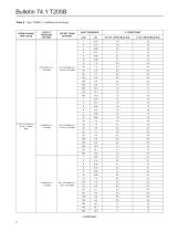
Bulletin 74.1:T205B Table 8. Type T205B Cv Coefficient (continued) SPRING RANGE AND COLOR OUTLET PRESSURE SETTING OFFSET FROM SETPOINT INLET PRESSURE 1 Inch / DN 25 Body Size 3/4 Inch / DN 20 Body Size
Open the catalog to page 8
Bulletin 74.1:T205B Table 8. Type T205B Cv Coefficient (continued) SPRING RANGE AND COLOR OUTLET PRESSURE SETTING OFFSET FROM SETPOINT INLET PRESSURE 1 Inch / DN 25 Body Size 3/4 Inch / DN 20 Body Size
Open the catalog to page 9
Bulletin 74.1:T205B Table 8. Type T205B Cv Coefficient (continued) SPRING RANGE AND COLOR OUTLET PRESSURE SETTING OFFSET FROM SETPOINT INLET PRESSURE 1 Inch / DN 25 Body Size 0.5 to 1.2 psig / 34 to 83 mbar Yellow 3/4 Inch / DN 20 Body Size
Open the catalog to page 10
Bulletin 74.1:T205B Table 8. Type T205B Cv Coefficient (continued) SPRING RANGE AND COLOR OUTLET PRESSURE SETTING OFFSET FROM SETPOINT INLET PRESSURE 1 Inch / DN 25 Body Size 1.2 psig to 2.5 psig / 83 to 172 mbar Green 3/4 Inch / DN 20 Body Size
Open the catalog to page 11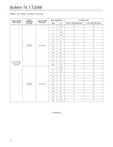
Bulletin 74.1:T205B Table 8. Type T205B Cv Coefficient (continued) SPRING RANGE AND COLOR OUTLET PRESSURE SETTING OFFSET FROM SETPOINT INLET PRESSURE 1 Inch / DN 25 Body Size 2.5 to 4.5 psig / 0.17 to 0.31 bar Light Blue 3/4 Inch / DN 20 Body Size
Open the catalog to page 12
Bulletin 74.1:T205B Table 8. Type T205B Cv Coefficient (continued) SPRING RANGE AND COLOR OUTLET PRESSURE SETTING OFFSET FROM SETPOINT INLET PRESSURE 1 Inch / DN 25 Body Size 3/4 Inch / DN 20 Body Size
Open the catalog to page 13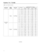
Bulletin 74.1:T205B Table 9. Type T205B Flow Capacities SPRING RANGE AND COLOR OUTLET PRESSURE SETTING OFFSET FROM SETPOINT INLET PRESSURE CAPACITIES IN SCFH / Nm3h OF AIR 3/4 Inch / DN 20 Body Size 1 Inch / DN 25 Body Size 1.0 to 2.5 inches w.c. / 2.5 to 6.2 mbar Orange
Open the catalog to page 14
Bulletin 74.1:T205B Table 9. Type T205B Flow Capacities (continued) SPRING RANGE AND COLOR OUTLET PRESSURE SETTING OFFSET FROM SETPOINT INLET PRESSURE CAPACITIES IN SCFH / Nm3h OF AIR 3/4 Inch / DN 20 Body Size 1 Inch / DN 25 Body Size Nm3h
Open the catalog to page 15
Bulletin 74.1:T205B Table 9. Type T205B Flow Capacities (continued) SPRING RANGE AND COLOR OUTLET PRESSURE SETTING OFFSET FROM SETPOINT INLET PRESSURE CAPACITIES IN SCFH / Nm3h OF AIR 3/4 Inch / DN 20 Body Size 1 Inch / DN 25 Body Size Nm3h
Open the catalog to page 16All FISHER REGULATORS catalogs and technical brochures
 ™ Control Valves and Instruments
16 Pages
 Run with higher performing,
16 Pages
 R Series
2 Pages
 LP-Gas Technologies
118 Pages
 Industrial Regulators
2 Pages
 Type 92B Pressure Reducing Valve
16 Pages
 Type 630R Relief Valve
8 Pages
 Fisher™ 585C Piston Actuators
16 Pages
 Type 630 Regulator
16 Pages
 Fisher™ YD and YS Control Valves
24 Pages
 easy-e Cryogenic Valves
12 Pages
 Large ET and ED Valves
20 Pages
 1305 Series Regulators
4 Pages
 H200 Series Relief Valves
4 Pages
 Air Application Map
1 Page
 DeltaV Controller Firewall
11 Pages
 CSI 6500 Overview
12 Pages
 The Criticality of Cooling
5 Pages
 Ovation Security Center
4 Pages
 DeltaV Smart Switches
28 Pages
 Smartprocess™ Heater
5 Pages
 FPSO Industry Solution
2 Pages
 LP-31
LP-3196 Pages
 CS 200 series
2 Pages
 Regulators Mini Catalog
24 Pages
 1301F, 1301G
12 Pages
 MR95 and MR98
2 Pages
 Fisher® D and DA Valves
12 Pages
 Fisher® EZ easy-e Control Valve
40 Pages
 Fisher® YD and YS Control Valves
24 Pages
 Fisher® HPNS Control Valve
36 Pages
 Fisher® HP Series Control Valves
28 Pages
 Fisher® CAV4 Control Valve
28 Pages
 Fisher® 377 Trip Valve
20 Pages
 EZR Pressure Reducing Regulator
36 Pages
 630 Regulator
16 Pages
 627F Pressure Reducing Regulator
12 Pages
 ACE97 Pad-Depad Valve
16 Pages
 310A Pressure Reducing Regulator
16 Pages
 S200 series
32 Pages
 R622 series
8 Pages
 Type HSR Pressure Regulators
20 Pages
 cs200 series
40 Pages
 CS400 Series
60 Pages
 167D Series Switching Valves
8 Pages


Archived catalogs
 Pressure Equivalents
1 Page
 Pipe and Tubing Sizing
1 Page


- SARRALLE manual valve
- SARRALLE control valve
- SARRALLE stainless steel valve
- SARRALLE ball valve
- SARRALLE pneumatic valve
- Threaded valve
- SARRALLE regulating valve
- Flange valve
- SARRALLE shut-off valve
- SARRALLE electric valve
- ISO valve
- Level limit switch
- Pressure gauge
- SARRALLE pressure regulator
- SARRALLE gas valve
- Valve with handwheel
- Liquid level detector
- SARRALLE pneumatically-operated valve
- SARRALLE level sensor