
- Catalogs
- FISHER REGULATORS
- T205 Series Tank Blanketing Regulators

T205 Series Tank Blanketing Regulators

T205 Series Tank Blanketing Regulators
The T205 Series Tank Blanketing Regulator is designed for low-pressure settings and quick response to pressure changes. It ensures precise control with minimal lockup pressure, is suitable for arctic conditions, and can handle gases like air, nitrogen, and natural gas. It is corrosion-resistant and meets FDA/USP Class VI standards for clean applications. The regulator is easily convertible between types and can be used for sour gas service.
The T205 Series is a direct-operated, spring-loaded regulator that prevents vaporization of stored liquids, reduces combustibility, and prevents oxidation or contamination. It maintains positive pressure to prevent tank collapse during pump-out operations. Available configurations include Types T205 and T205H for internal pressure registration, and Types T205M and T205HM for external pressure registration.
The regulator manages vapor space pressure over stored liquids. When tank pressure decreases, the actuator diaphragm senses the change, adjusting the valve disk to maintain pressure. When pressure increases, the valve disk reduces gas flow.
The T205 Series offers various configurations with different pressure ranges and materials. It is available in body sizes of 3/4 or 1 inch, with maximum allowable inlet pressures detailed in tables. Materials include gray cast iron, carbon steel, and stainless steel, with temperature capabilities from -76°F to 300°F depending on the material.
The regulator can be installed in any position, with specific orientations recommended for optimal performance. Types T205M and T205HM require a downstream control line to prevent condensation buildup.
Overpressure protection is necessary if inlet pressure exceeds outlet pressure ratings. Guidance on relief valve capacity requirements is provided.
Capacity tables are based on air with a specific gravity of 1.0. Conversion factors are provided for other gases, allowing adjustments based on specific gravity and temperature.
Detailed ordering information and guides are provided, including part numbers and configurations for different applications.
The document provides detailed flow capacity data for the T205 Series, specifically for Types T205M and T205HM. It includes specifications for different body sizes and orifice sizes, focusing on spring range, outlet pressure settings, and inlet pressure capacities.
The document outlines various spring ranges and their corresponding colors, such as Yellow (0.5 to 1.2 psig), Green (1.2 to 2.5 psig), Light Blue (2.5 to 4.5 psig), and others. Each range is associated with specific outlet pressure settings and offsets from the setpoint.
The tables provide flow capacities in SCFH (Standard Cubic Feet per Hour) and Nm3/h (Normal Cubic Meters per Hour) for different orifice sizes ranging from 1/8 inch to 9/16 inch. Capacities are detailed for various inlet pressures and categorized by spring range and color.
Black areas in the tables indicate where the desired flow capacity is not obtainable for a given inlet pressure. Shaded areas indicate where the maximum operating inlet pressure for a given orifice size is exceeded.
The document provides comprehensive data for selecting appropriate configurations based on specific pressure and flow requirements, ensuring optimal performance and safety in applications using the T205 Series.
Catalog excerpts

T205 Series Tank Blanketing Regulators Figure 1. Type T205 Tank Blanketing Regulator Contents Features . . . . . . . . . . . . . . . . . . . . . . . . . . . . . . . . . . . . . . . . 1 Introduction. . . . . . . . . . . . . . . . . . . . . . . . . . . . . . . . . . . . . . 1 Specifications . . . . . . . . . . . . . . . . . . . . . . . . . . . . . . . . . . . . 2 Principle of Operation . . . . . . . . . . . . . . . . . . . . . . . . . . . . . . 2 Installation. . . . . . . . . . . . . . . . . . . . . . . . . . . . . . . . . . . . . . . 6 Overpressure Protection. . . . . . . . . . . . . . . . . . . . . . . . . . . . 6 Capacity Information. . . . . . . . . . . . . . . . . . . . . . . . . . . . . . . 6 Ordering Information. . . . . . . . . . . . . . . . . . . . . . . . . . . . . . 31 Ordering Guide . . . . . . . . . . . . . . . . . . . . . . . . . . . . . . . . . . 31 Features Low-pressure setting and fast speed of response – T205 Series regulator has a low-pressure setting as low as 1 in. w.c. / 2.5 mbar. It can respond quickly to downstream flow demand and pressure changes due to direct-operated structure. Accurate control and small lockup pressure – Large diaphragm area provides very accurate throttling control at low pressure settings. An added benefit of lever style regulator is that it can shut off the process fluid using small lockup pressure. Arctic Temperatures – Constructions for process temperatures as low as -76°F / -60°C available by request. Multiple applications – T205 Series regulator can be used for a wide variety of gases including air, nitrogen, natural gas, sour gas (NACE Construction), butane and propane. Corrosion resistance – Multiple regulator constructions are available in a variety of materials for compatibility with corrosive process gases. FDA/USP Class VI – Types T205 and T205M can be used in applications requiring clean regulator solutions. Constructions available with FDA and USP Class VI approved elastomers. Easy conversion between constructions – Converts easily from the Types T205 and T205M to the Types T205H and T205HM with two O-rings and one machine screw. Sour gas service capability – Available construction to meet NACE MR0175-2002. Introduction T205 Series tank blanketing regulator is a direct-operated and spring-loaded regulator (Figure 1). The regulator prevents a stored liquid from vaporizing into the atmosphere, reduces liquid combustibility and prevents oxidation or contamination of the product by reducing its exposure to air. T205 Series maintains a slightly positive pressure and thereby reduces the possibility of tank wall collapse during pump out operation. T205 Series is available in two configurations: Types T205 and T205H for internal pressure registration and Types T205M and T205HM for ex
Open the catalog to page 1
T205 Series Specifications The Specifications section on this page provides the ratings and other specifications for the T205 Series. Factory specification such as type, maximum inlet pressure, maximum temperature, maximum outlet pressure, spring range and orifice size are stamped on the nameplate fastened on the regulator at the factory. Product Configurations Type T205: Tank blanketing regulator with outlet pressure range of 1 in. w.c. to 7 psig / 2.5 mbar to 0.48 bar in seven different spring ranges and has internal pressure registration requiring no downstream control line Type T205M: Similar...
Open the catalog to page 2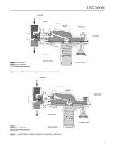
T205 Series VALVE DISK LEVER PUSHER POST PIPE PLUG PITOT TUBE INLET PRESSURE CONTROL SPRING OUTLET PRESSURE ATMOSPHERIC PRESSURE Figure 2. Type T205 with Internal Registration Operational Schematic VALVE DISK O-RING STEM SEAL PUSHER POST CONTROL LINE CONNECTION THROAT SEAL TYPE Y602-1 VENT INLET PRESSURE OUTLET PRESSURE CONTROL SPRING ATMOSPHERIC PRESSURE Figure 3. Type T205M with External Registration Operational Schematic
Open the catalog to page 3
T205 Series HORIZONTAL PIPELINE VENT POINTED DOWN DOWNSTREAM CONTROL LINE HORIZONTAL PIPELINE INLET PRESSURE OUTLET PRESSURE ATMOSPHERIC PRESSURE DOWNSTREAM CONTROL PRESSURE Figure 4. T205 Series Actuator Casing Drainage Schematic POSITION 3 POSITION 1 (STANDARD) BODY POSITION D POSITION 3 POSITION 1 (STANDARD) BODY POSITION C A (STANDARD) VENT POSITION POSITION 3 BODY POSITION BODY POSITION Figure 5. Body and Vent Orientation C
Open the catalog to page 4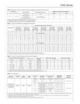
T205 Series Table 1. Body Sizes, End Connection Styles and Maximum Allowable Inlet Pressure BODY SIZE MAXIMUM ALLOWABLE INLET PRESSURE BODY MATERIAL Gray cast iron LCC Carbon steel CF8M/CF3M Stainless steel 1. All flanges are welded. Weld-on flange dimension is 14 in. / 356 mm face-to-face. 2. Pipe nipples and flanges are 316 Stainless steel for flanged body assemblies. 3. Inlet pressure is limited to 150 psig / 10.3 bar for Types T205H and T205HM. Table 2. T205 Series Maximum Operating Inlet Pressure MAXIMUM OPERATING INLET PRESSURE(1) ORIFICE SIZE 1 to 2.5 In. w.c. / 2.5 to 6.2 mbar Outlet...
Open the catalog to page 5
T205 Series Table 5. Flow Coefficients ORIFICE SIZE FLOW COEFFICIENTS (WIDE-OPEN) Table 6. Correction Factors (For converting Air Flow Rates to Other Gas Flow Rates)(1) BLANKET GAS SPECIFIC GRAVITY CORRECTION FACTOR 1. For gases of other specific gravities, use equation below. 1.00 Correction Factor = SG Installation The regulator may be installed in any position as long as the flow through the body is in the direction indicated by the arrow on the body when using a T205 Series regulator. To achieve the published capacities at low setpoint, the spring case barrel should be installed pointed down...
Open the catalog to page 6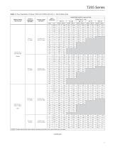
T205 Series Table 7. Flow Capacities of Types T205 and T205H with 3/4 in. / DN 20 Body Size SPRING RANGE AND COLOR OUTLET PRESSURE SETTING OFFSET FROM SETPOINT INLET PRESSURE CAPACITIES IN SCFH / Nm3/h OF AIR Orifice Size, In. / mm 1/8 / 3.2 - Shaded areas indicate where maximum operating inlet pressure for a given orifice size is exceeded.
Open the catalog to page 7
T205 Series Table 7. Flow Capacities of Types T205 and T205H with 3/4 in. / DN 20 Body Size (continued) SPRING RANGE AND COLOR OUTLET PRESSURE SETTING OFFSET FROM SETPOINT INLET PRESSURE CAPACITIES IN SCFH / Nm3/h OF AIR Orifice Size, In. / mm 1/8 / 3.2 - Shaded areas indicate where maximum operating inlet pressure for a given orifice size is exceeded.
Open the catalog to page 8All FISHER REGULATORS catalogs and technical brochures
 Fisher™ 8590 High-Performance
16 Pages
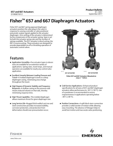 bulletin-fisher-657-and-667
16 Pages
Archived catalogs
 167D Series Switching Valves
8 Pages
 CS400 Series
60 Pages
 cs200 series
40 Pages
 Type HSR Pressure Regulators
20 Pages
 R622 series
8 Pages
 S200 series
32 Pages
 310A Pressure Reducing Regulator
16 Pages
 ACE97 Pad-Depad Valve
16 Pages
 627F Pressure Reducing Regulator
12 Pages
 630 Regulator
16 Pages
 EZR Pressure Reducing Regulator
36 Pages
 Fisher® 377 Trip Valve
20 Pages
 Fisher® CAV4 Control Valve
28 Pages
 Fisher® HP Series Control Valves
28 Pages
 Fisher® HPNS Control Valve
36 Pages
 Fisher® YD and YS Control Valves
24 Pages
 Fisher® EZ easy-e Control Valve
40 Pages
 Fisher® D and DA Valves
12 Pages
 MR95 and MR98
2 Pages
 1301F, 1301G
12 Pages
 Regulators Mini Catalog
24 Pages
 CS 200 series
2 Pages
 LP-31
LP-3196 Pages
 FPSO Industry Solution
2 Pages
 Smartprocess™ Heater
5 Pages
 DeltaV Smart Switches
28 Pages
 Ovation Security Center
4 Pages
 The Criticality of Cooling
5 Pages
 CSI 6500 Overview
12 Pages
 DeltaV Controller Firewall
11 Pages
 Air Application Map
1 Page
 H200 Series Relief Valves
4 Pages
 1305 Series Regulators
4 Pages
 Large ET and ED Valves
20 Pages
 easy-e Cryogenic Valves
12 Pages
 Fisher™ YD and YS Control Valves
24 Pages
 Type 630 Regulator
16 Pages
 Fisher™ 585C Piston Actuators
16 Pages
 Type 630R Relief Valve
8 Pages
 Type 92B Pressure Reducing Valve
16 Pages
 Industrial Regulators
2 Pages
 LP-Gas Technologies
118 Pages
 R Series
2 Pages
 Run with higher performing,
16 Pages
 ™ Control Valves and Instruments
16 Pages
 Pressure Equivalents
1 Page
 Pipe and Tubing Sizing
1 Page


- Manual valve
- FISHER control valve
- FISHER stainless steel valve
- Ball valve
- FISHER pneumatic valve
- Threaded valve
- Regulating valve
- Flange valve
- On/off valve
- Electric valve
- ISO valve
- Pressure gauge
- Level limit switch
- FISHER pressure regulator
- Gas valve
- Valve with handwheel
- FISHER pneumatically-operated valve
- Liquid level detector
- Butterfly valve