- Catalogs
- FISHER REGULATORS
- R600 and HSRL Series Instruction Manual
R600 and HSRL Series Instruction Manual
1 /8Pages

R600 and HSRL Series Instruction Manual
1 /8Pages
Catalog excerpts
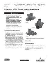
R600 and HSRL Series LP-Gas Regulators Instruction Manual MCK 2141 October 2015 R600 and HSRL Series Instruction Manual ! Failure to follow these instructions or to properly install and maintain this equipment could result in an explosion and/or fire causing property damage and personal injury or death. Fisher® equipment must be installed, operated and maintained in accordance with federal, state and local codes and Fisher instructions. The installation in most states must also comply with NFPA No. 54 and 58 standards. Only personnel trained in the proper procedures, codes, standards and regulations of the LP-Gas industry should install and service this equipment. Things to tell the gas customer: 1. how the customer the vent or vent assembly or vent S tube. Stress that this opening must remain unobstructed at all times. Tell the customer to check the vent opening after a freezing rain, sleet storm or snow to make sure ice has not formed in the vent. 2. how the customer the shutoff valve on the container. S The customer should close this valve immediately if gas is smelled, appliance pilot lights fail to stay on or appear higher than usual or any other abnormal situation occurs. 3. ell the customer to call your company to service the T regulator if the regulator vents gas or a leak develops in the system. Only a qualified gas service person should install or service the regulator. Figure 1. Types R622, R642 and HSRL Series Regulators Introduction Scope of the Manual This Instruction Manual covers Installation and Maintenance for the R600 and HSRL Series regulators, which includes first stage, second stage, two psig service, integral two- stage and integral two psig service regulators used on LP-Gas vapor service applications. They are not to be used on liquid service. 4. ell the customer to call your company to have a leak T check performed if the gas supply has been shutoff or interrupted for any reason. A leak check must be performed by a qualified gas service person on the piping system immediately after turning on the gas supply. TYPE HSRL
Open the catalog to page 1
R600 and HSRL Series LP-Gas Regulators Specifications Specifications section, Tables 1 and 2 list the specifications for these regulators. Contact the factory if the regulator is to be used on any service other than LP-Gas, natural gas or air. The following information is located on the spring case: Type number, orifice size, spring range and date of manufacture. Pressure Taps Size Restriction R600 Series: 1/8 in. NPT: #54 (0.055 in. / 1.40 mm) Drill on outlet and inlet HSRL Series: None Orifice Sizes R600 Series (Except R632A and R632E Series): 7/32 in. / 5.6 mm R632A and R632E Series: 0.256...
Open the catalog to page 2
R600 and HSRL Series LP-Gas Regulators Integral Two-stage Regulator The Type R632A integral two-stage regulator contains a non-adjustable first stage regulator on the inlet. The second stage provides 11 in. w.c. / 27 mbar outlet pressure. The second stage portion has a high capacity internal relief valve construction. The first stage does not have an internal relief valve. The regulators are normally painted GRAY with a BLACK CAP. VENT POINTED DOWN Integral Two psig Service Regulator The Type R632E integral two psig service regulator contains a non-adjustable first stage regulator on the inlet....
Open the catalog to page 3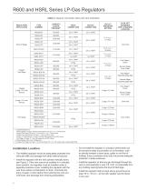
R600 and HSRL Series LP-Gas Regulators Table 2. Capacity, Connection Sizes and Vent Orientation TYPE NUMBER INLET CONNECTION OUTLET CONNECTION 1 in. FNPT 1/4 in. FNPT FPOL 1/4 in. FNPT R632E-BCH Integral 2 psig / 0.14 bar Service 1/2 in. FNPT 2 psig / 0.14 bar 3/4 in. FNPT First Stage(3): Down Second Stage: Over Outlet First Stage(3): Opposite gauge taps Second Stage: Opposite gauge taps First Stage(3): Down Second Stage: Over Outlet Over Inlet 10 psig / 0.69 bar Over Outlet Over Inlet OUTLET PRESSURE SETTING 3/4 IN. NPT SCREENED VENT STANDARD LOCATION REGULATOR APPLICATION S econd Stage: 10...
Open the catalog to page 4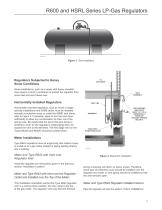
R600 and HSRL Series LP-Gas Regulators Figure 3. Tank Installation Regulators Subjected to Heavy Snow Conditions Some installations, such as in areas with heavy snowfall, may require a hood or enclosure to protect the regulator from snow load and vent freeze over. VENT ASSEMBLY Horizontally Installed Regulators Horizontally mounted regulators, such as found in single cylinder installations and ASME tanks, must be installed beneath a protective cover or under the ASME tank dome, refer to Figure 3. If possible, slope or turn the vent down sufficiently to allow any condensation to drain out of the...
Open the catalog to page 5
R600 and HSRL Series LP-Gas Regulators END OF REGULATOR VENT TUBE LOCATED AT TOP INSIDE OF HOUSING DOME COVER GRADE GROUND DOWNWARD AND SLOPING AWAY FROM HOUSING DOME. THIS PREVENTS WATER COLLECTING AND RUNNING INTO OR STANDING AROUND HOUSING DOME. REGULATOR ADJUSTMENT CLOSURE CAP MUST BE TIGHT. WATER MARK LEFT IN HOUSING DOME AT LEVEL ABOVE REGULATOR VENT OR END OF VENT TUBE REQUIRES REPLACEMENT OF REGULATOR. INSTALL REGULATOR PROPERLY. T14448-A2 Figure 5. Underground Installation Indoor Installations By code, regulators installed indoors have limited inlet pressure and they require a vent line...
Open the catalog to page 6
R600 and HSRL Series LP-Gas Regulators The inlet and outlet pressure plug may be removed using a 7/16 in. / 11 mm hexagon wrench. The pressure tap is restricted, so the plug can be removed with pressure on the outlet of the regulator. Install a pressure gauge to determine the regulator’s inlet pressure and outlet setting during adjustment, (actual pressure at the second stage regulator may be less due to line loss). After setting, add thread sealant to the 1/8 in. NPT pipe plugs. Reinstall the pipe plugs by threading into the gauge ports finger-tight and then wrench tighten 1-1/2 to 3 turns past...
Open the catalog to page 7
R600 and HSRL Series LP-Gas Regulators Vent Opening Make sure the regulator vent, vent assembly or vent tube does not become plugged by mud, insects, ice, snow, paint, etc. The vent screen aids in keeping the vent from becoming plugged and the screen should be clean and properly installed. Make sure any irrigation system operated near a regulator or vent line does not spray water into the vent opening of the regulator or vent assembly. Water Inside Regulators from Floods, Weather or Water Table on Underground Systems Replace any regulator that had water in their spring case, has been flooded,...
Open the catalog to page 8All FISHER REGULATORS catalogs and technical brochures
 ™ Control Valves and Instruments
16 Pages
 Run with higher performing,
16 Pages
 R Series
2 Pages
 LP-Gas Technologies
118 Pages
 Industrial Regulators
2 Pages
 Type 92B Pressure Reducing Valve
16 Pages
 Type 630R Relief Valve
8 Pages
 Fisher™ 585C Piston Actuators
16 Pages
 Type 630 Regulator
16 Pages
 Fisher™ YD and YS Control Valves
24 Pages
 easy-e Cryogenic Valves
12 Pages
 Large ET and ED Valves
20 Pages
 1305 Series Regulators
4 Pages
 H200 Series Relief Valves
4 Pages
 Air Application Map
1 Page
 DeltaV Controller Firewall
11 Pages
 CSI 6500 Overview
12 Pages
 The Criticality of Cooling
5 Pages
 Ovation Security Center
4 Pages
 DeltaV Smart Switches
28 Pages
 Smartprocess™ Heater
5 Pages
 FPSO Industry Solution
2 Pages
 LP-31
LP-3196 Pages
 CS 200 series
2 Pages
 Regulators Mini Catalog
24 Pages
 1301F, 1301G
12 Pages
 MR95 and MR98
2 Pages
 Fisher® D and DA Valves
12 Pages
 Fisher® EZ easy-e Control Valve
40 Pages
 Fisher® YD and YS Control Valves
24 Pages
 Fisher® HPNS Control Valve
36 Pages
 Fisher® HP Series Control Valves
28 Pages
 Fisher® CAV4 Control Valve
28 Pages
 Fisher® 377 Trip Valve
20 Pages
 EZR Pressure Reducing Regulator
36 Pages
 630 Regulator
16 Pages
 627F Pressure Reducing Regulator
12 Pages
 ACE97 Pad-Depad Valve
16 Pages
 310A Pressure Reducing Regulator
16 Pages
 S200 series
32 Pages
 R622 series
8 Pages
 Type HSR Pressure Regulators
20 Pages
 cs200 series
40 Pages
 CS400 Series
60 Pages
 167D Series Switching Valves
8 Pages


Archived catalogs
 Pressure Equivalents
1 Page
 Pipe and Tubing Sizing
1 Page


- SARRALLE manual valve
- SARRALLE control valve
- SARRALLE stainless steel valve
- SARRALLE ball valve
- SARRALLE pneumatic valve
- Threaded valve
- SARRALLE regulating valve
- Flange valve
- SARRALLE shut-off valve
- SARRALLE electric valve
- ISO valve
- Level limit switch
- SARRALLE pressure regulator
- SARRALLE gas valve
- Valve with handwheel
- Liquid level detector
- SARRALLE pneumatically-operated valve
- SARRALLE level sensor