
- Catalogs
- FISHER REGULATORS
- Fisher® HPNS Control Valve

Fisher® HPNS Control Valve

Fisher® HPNS Control Valve
This manual provides comprehensive guidance on the installation, maintenance, and parts information for HPNS valves, which range from NPS 1/2 to NPS 8 with CL900 to CL2075 ratings. Proper training and qualification are essential to handle these valves safely and effectively.
HPNS valves are engineered for high seismic environments and feature buttweld end connections. They are compatible with Fisher 667NS2 and 657NS2 actuators.
The valves support buttwelding consistent with Schedule 40-160, without flange or socket welding options. They offer various flow characteristics and shutoff classifications, including Class IV and V for bore seal trim. Special tools are required for assembly, particularly for bore seal plugs.
HPNS valves control fluid flow through a plug-stem assembly that moves axially within a cage. The valve opens or closes by moving the plug to engage or disengage with the seat ring, thus controlling the fluid flow.
Proper lifting techniques using eyebolts are crucial to prevent injury or damage. Detailed instructions are provided for lifting valve/actuator assemblies, valves only, and actuators only.
Installation requires careful inspection and cleaning of the valve body and pipelines. The flow direction must match the arrow on the valve body. Post-weld heat treatment may be necessary depending on the materials used.
Regular maintenance is crucial for optimal performance. Detailed procedures are included for bonnet nut torquing, packing lubrication, and replacement of conventional and HIGH-SEAL packing.
The manual provides guidance to address common operational issues.
Instructions for ordering replacement parts are included, along with a comprehensive parts list.
- Personal injury could result from packing leakage. Ensure proper adjustment of valve packing to meet service conditions.
- Before disassembly, ensure the valve is not pressurized, and all safety measures are in place to prevent sudden release of pressure or process fluid.
- Use protective gear and follow lock-out procedures to maintain safety during maintenance.
- Regular inspection and replacement of valve parts are necessary due to normal wear. The frequency depends on service conditions.
- Maintenance can be performed with the valve in the line, but ensure all safety precautions are followed.
- If leakage occurs, tighten the packing flange nuts to the recommended torque. If leakage persists, replace the packing.
- Inspect the valve plug stem and packing box wall for damage if leakage continues.
- Isolate the valve from line pressure and ensure all pressure is relieved before starting.
- Follow a step-by-step procedure to remove and replace the packing, ensuring all parts are clean and free from damage.
- Use new gaskets upon reassembly to ensure proper sealing.
- Follow similar steps as conventional packing replacement, with additional steps for removing and installing specific components like Belleville springs and load scales.
- Do not reuse spiral-wound gaskets; always replace them to ensure a proper seal.
- Use only approved replacement parts to avoid valve damage.
- Proper torquing procedures are essential to prevent damage and ensure safety.
Detailed procedures are provided for removing and replacing trim components, including the use of specific tools and techniques to ensure proper assembly and sealing.
The document provides detailed specifications for the Flow Up Bore Seal Installation Tool, including dimensions for different plug sizes. It references Data Sheets for the AP1000 Power Plant Design and includes part numbers for ordering tools.
Common issues with the Fisher HPNS Valve are addressed, such as packing leakage, body to bonnet leakage, and valve stroke problems. Solutions include verifying packing torque, inspecting sealing surfaces, and replacing damaged parts.
Several figures illustrate the installation and configuration of the HPNS Valve, including the retainer guiding the bore seal onto the plug and staking the threads of the bore seal retainer.
Instructions for ordering replacement parts emphasize using genuine Fisher parts to avoid warranty voidance and performance issues. A comprehensive parts list is provided, with part numbers for recommended spares.
The document outlines recommended spare parts, their classification, and replacement rationale. It suggests maintenance schedules based on service conditions and emphasizes the importance of routine maintenance to ensure valve performance.
Several tables provide detailed information on spare parts, including part numbers, quantities, and maintenance recommendations. The tables cover various components such as packing rings, gaskets, and cages for different valve sizes.
Regular maintenance is highlighted as crucial for valve performance, with specific intervals for replacing components like packing rings and gaskets. Safety warnings stress the use of genuine parts to prevent personal injury and property damage.
Catalog excerpts

Instruction Manual HPNS Valve Fisherr HPNS Control Valve Contents Figure 1. HPNS Valve with 667NS2 Actuator Introduction . . . . . . . . . . . . . . . . . . . . . . . . . . . . . . . . . 1 Scope of Manual . . . . . . . . . . . . . . . . . . . . . . . . . . . . . 1 Description . . . . . . . . . . . . . . . . . . . . . . . . . . . . . . . . . 1 Specifications . . . . . . . . . . . . . . . . . . . . . . . . . . . . . . . 1 Educational Services . . . . . . . . . . . . . . . . . . . . . . . . . 2 Principle of Operation . . . . . . . . . . . . . . . . . . . . . . . . . 4 Lifting Guidelines . . . . . . . . . . . . . . . . . . . . . . . . . . . . . 5 Installation . . . . . . . . . . . . . . . . . . . . . . . . . . . . . . . . . . 6 Maintenance . . . . . . . . . . . . . . . . . . . . . . . . . . . . . . . . . 7 Bonnet Nut Torquing Considerations . . . . . . . . . . . 8 Packing Lubrication . . . . . . . . . . . . . . . . . . . . . . . . . . 9 Packing Maintenance . . . . . . . . . . . . . . . . . . . . . . . . . 9 Replacing Conventional Packing . . . . . . . . . . . . 9 Replacing HIGH-SEAL Packing . . . . . . . . . . . . . 14 Trim Removal . . . . . . . . . . . . . . . . . . . . . . . . . . . . . . 16 Standard Balanced and Unbalanced Trim Removal . . . . . . . . . . . . . . . . . . . . . . . . 16 Bore Seal Trim Removal . . . . . . . . . . . . . . . . . . 16 Trim Replacement . . . . . . . . . . . . . . . . . . . . . . . . . . 17 Installing Bore Seal Trim . . . . . . . . . . . . . . . . . . . . . 20 Troubleshooting . . . . . . . . . . . . . . . . . . . . . . . . . . . . . 22 Parts Ordering . . . . . . . . . . . . . . . . . . . . . . . . . . . . . . . 28 Parts List . . . . . . . . . . . . . . . . . . . . . . . . . . . . . . . . . . . 28 Introduction Scope of Manual This instruction manual includes installation, maintenance, and parts information for NPS 1/2 through NPS 8 HPNS valves with CL900 through CL2075 ratings. Note: Applications requiring lower pressure class ratings may use the same casting as a higher rated valve of the required size. Refer to separate manuals for instructions covering the actuator, positioner, and accessories. Do not install, operate, or maintain HPNS valves without being fully trained and qualified in valve, actuator, and accessory installation, operation, and maintenance. To avoid personal injury or property damage, it is important to carefully read, understand, and follow all the contents of this manual, including all safety cautions and warnings. If you have any questions about these instructions, contact your Emerson Process Management sales office before proceeding. Description HPNS valves (figure 1) have buttweld end connections in various schedules and are designed for use with Fisher 667NS2 and 657NS2 actuators. HPNS valves are designed to handle high seismic environments. Specifications Specifications for the HPNS valves are shown in table 1.
Open the catalog to page 1
Instruction Manual HPNS Valve Table 1. Specifications End Connection Styles and Ratings(1,2) Buttwelding: Consistent with Schedule 40-160 Flow Direction Standard Cage J HPNS Balanced: Normally flow up J HPNS Unbalanced: Normally flow down or up(3) Socket Welding: Not available Cavitrol III Cage: Flow down Whisper Trim III Cage: Flow up Approximate Weights (valve body and bonnet assemblies) Shutoff Classifications See table 3 Bidirectional Trim: Class V. See table 4 Bore Seal trim: High-temperature, Class IV and V. See table 4 See table 2 Bolt Torque Tolerance Torque values given are +/- 5%, unless...
Open the catalog to page 2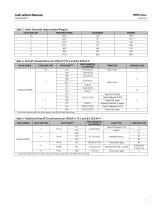
Instruction Manual HPNS Valve Table 2. Valve Assembly Approximate Weights VALVE SIZE, NPS PRESSURE RATING Table 3. Shutoff Classifications per ANSI/FCI 70-2 and IEC 60534-4 PORT DIAMETER, mm (INCHES) TRIM STYLE LEAKAGE CLASS VALVE DESIGN Unbalanced HPNS 1. Data Sheet Number refers to PV14 Data Sheets for the AP1000 Power Plant Design. Table 4. Additional Shutoff Classification per ANSI/FCI 70-2 and IEC 60534-4 VALVE DESIGN PORT DIAMETER, mm (INCHES) CAGE STYLE Linear (Whisper III, C3) Modified Equal % LEAKAGE CLASS 1. Data Sheet Number refers to PV14 Data Sheets and PV69 Data Sheets for the AP1000...
Open the catalog to page 3
Instruction Manual HPNS Valve Table 5. Recommended Torque for Packing Flange Nuts (non live-loaded) TORQUE 115 1. Data Sheet Number refers to PV14 Data Sheets for the AP1000 Power Plant Design. Table 6. Torque for Body-to-Bonnet Bolting Using Nuclear Grade Never-Seezr Lubricant TORQUE Principle of Operation HPNS valves are control valves based on the Fisher HP valve product. The valve body and bonnet contain a fluid under pressure, while the internal valve parts control the flow of the fluid through the valve. The internal parts consist of gaskets, a seat ring, a plugstem assembly, and a cage....
Open the catalog to page 4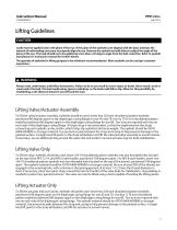
HPNS Valve July 2014 Lifting Guidelines CAUTION Loads must be applied only in the plane of the eye. If the plane of the eyebolt is not aligned with the load, estimate the amount of unthreading necessary to properly align the eye. Remove the eyebolt and add shims to adjust the angle of the plane of the eye. The load should never be applied at more than a 45 degree angle from the bolt centerline. Refer to eyebolt manufacturer's instruction manual for further details. The quantity of eyebolts for lifting purpose is the minimum recommendation. More eyebolts can be used per customer experience. WARNING...
Open the catalog to page 5
HPNS Valve Instruction Manual Installation WARNING Always wear protective gloves, clothing, and eyewear when performing any installation operations to avoid personal injury. Personal injury or equipment damage caused by sudden release of pressure may result if the valve assembly is installed where service conditions could exceed the limits given in table 1 or on the appropriate nameplates. To avoid such injury or damage, provide a relief valve for over-pressure protection as required by government or accepted industry codes and good engineering practices. Check with your process or safety engineer...
Open the catalog to page 6
Instruction Manual HPNS Valve 3. Flow through the valve must be in the direction indicated by the flow arrow, which is stamped on or attached to the valve body. CAUTION Depending on valve body materials used, post-weld heat treating might be needed. Post-weld heat treatment can damage internal elastomeric, plastic, and metal parts. Shrink-fit pieces and threaded connections might also loosen. In general, if post-weld heat treating is needed, remove all trim parts. Contact your Emerson Process Management sales office for additional information. 4. Use accepted piping and welding practices when...
Open the catalog to page 7All FISHER REGULATORS catalogs and technical brochures
 Fisher™ 8590 High-Performance
16 Pages
 bulletin-fisher-657-and-667
16 Pages
Archived catalogs
 167D Series Switching Valves
8 Pages
 CS400 Series
60 Pages
 cs200 series
40 Pages
 Type HSR Pressure Regulators
20 Pages
 R622 series
8 Pages
 S200 series
32 Pages
 310A Pressure Reducing Regulator
16 Pages
 ACE97 Pad-Depad Valve
16 Pages
 627F Pressure Reducing Regulator
12 Pages
 630 Regulator
16 Pages
 EZR Pressure Reducing Regulator
36 Pages
 Fisher® 377 Trip Valve
20 Pages
 Fisher® CAV4 Control Valve
28 Pages
 Fisher® HP Series Control Valves
28 Pages
 Fisher® YD and YS Control Valves
24 Pages
 Fisher® EZ easy-e Control Valve
40 Pages
 Fisher® D and DA Valves
12 Pages
 MR95 and MR98
2 Pages
 1301F, 1301G
12 Pages
 Regulators Mini Catalog
24 Pages
 CS 200 series
2 Pages
 LP-31
LP-3196 Pages
 FPSO Industry Solution
2 Pages
 Smartprocess™ Heater
5 Pages
 DeltaV Smart Switches
28 Pages
 Ovation Security Center
4 Pages
 The Criticality of Cooling
5 Pages
 CSI 6500 Overview
12 Pages
 DeltaV Controller Firewall
11 Pages
 Air Application Map
1 Page
 H200 Series Relief Valves
4 Pages
 1305 Series Regulators
4 Pages
 Large ET and ED Valves
20 Pages
 easy-e Cryogenic Valves
12 Pages
 Fisher™ YD and YS Control Valves
24 Pages
 Type 630 Regulator
16 Pages
 Fisher™ 585C Piston Actuators
16 Pages
 Type 630R Relief Valve
8 Pages
 Type 92B Pressure Reducing Valve
16 Pages
 Industrial Regulators
2 Pages
 LP-Gas Technologies
118 Pages
 R Series
2 Pages
 Run with higher performing,
16 Pages
 ™ Control Valves and Instruments
16 Pages
 Pressure Equivalents
1 Page
 Pipe and Tubing Sizing
1 Page


- Manual valve
- FISHER stainless steel valve
- Ball valve
- FISHER pneumatic valve
- Threaded valve
- Regulating valve
- Flange valve
- On/off valve
- Electric valve
- ISO valve
- Pressure gauge
- Level limit switch
- FISHER pressure regulator
- Gas valve
- Valve with handwheel
- FISHER pneumatically-operated valve
- Liquid level detector
- Butterfly valve