Catalog excerpts

Instruction Manual Fisherr EWN Series and EW-1 Series Valves Contents Introduction . . . . . . . . . . . . . . . . . . . . . . . . . . . . . . . . . 1 Scope of Manual . . . . . . . . . . . . . . . . . . . . . . . . . . . . . 1 Description . . . . . . . . . . . . . . . . . . . . . . . . . . . . . . . . . 1 Specifications . . . . . . . . . . . . . . . . . . . . . . . . . . . . . . . 1 Educational Services . . . . . . . . . . . . . . . . . . . . . . . . . 3 Installation . . . . . . . . . . . . . . . . . . . . . . . . . . . . . . . . . . 3 Maintenance . . . . . . . . . . . . . . . . . . . . . . . . . . . . . . . . . 5 Packing Lubrication . . . . . . . . . . . . . . . . . . . . . . . . . . 5 Packing Maintenance . . . . . . . . . . . . . . . . . . . . . . . . . 6 Trim Removal . . . . . . . . . . . . . . . . . . . . . . . . . . . . . . 10 Lapping Seating Surfaces . . . . . . . . . . . . . . . . . . . . 11 Valve Plug Maintenance . . . . . . . . . . . . . . . . . . . . . 12 Parts Ordering . . . . . . . . . . . . . . . . . . . . . . . . . . . . . . . 14 Parts List . . . . . . . . . . . . . . . . . . . . . . . . . . . . . . . . . . . 14 Figure 1. Fisher EWNT-2 NPS 12 x 8 EWNT-2 Valve with Typical Actuator Introduction Scope of Manual This instruction manual includes installation, maintenance, and parts information for Fisher NPS 8 x 6 and 12 x 8 EWN Series and EW-1 Series valves (figure 1). Refer to separate manuals for instructions covering the actuator and accessories. Do not install, operate, or maintain an EWN or EW-1 Series valve without being fully trained and qualified in valve, actuator, and accessory installation, operation, and maintenance. To avoid personal injury or property damage, it is important to carefully read, understand, and follow all the contents of this manual, including all safety cautions and warnings. If you have any questions about these instructions, contact your Emerson Process Management sales office before proceeding. Description These single-port globe-style valves have cage guiding, threaded seat rings, metal-to-metal seating, and push-down-to-close valve plug action. Additional details are given in tables 1 and 2. Specifications Typical specifications for these valves are shown in table 1. Some of the specifications for a given valve assembly as it was shipped from the factory appear on the actuator nameplate if the valve is part of a complete control valve assembly.
Open the catalog to page 1
Instruction Manual Table 1. Specifications Available Configurations and Valve Body Sizes See table 2 End Connection Styles Whisper Trim™ Cages: Linear, except equal percentage for first 38.1 mm (1.5 inch) of travel with level D cage for NPS 8 x 6 valve Flow Directions Flanged Ends: Styles per ASME B16.5 are CL300, 600, or 900 J raised-face or J ring-type joint EWS-1 with Standard Cage: Normally up All Others with Standard Cages: Normally down Buttwelding Ends: Styles per ASME B16.25 are Schedule J 40 or J 80 for all CL300 and 600 valves or Schedule J 80, J 100, or J 120 for all CL900 valves...
Open the catalog to page 2
Instruction Manual Table 3. Shutoff Classification Per ANSI/FCI 70-2 and IEC 60534-4 Valve Shutoff Class IV (optional with extra piston rings) II (standard) III (optional for CL300 or CL600 valves only) V (optional, consult your Emerson Process Management sales office) IV (standard) Educational Services For information on available courses for the Fisher EWN series and EW-1 series valves, as well as a variety of other products, contact: Emerson Process Management Educational Services - Registration Phone: 1-641-754-3771 or 1-800-338-8158 E-mail: education@emerson.com...
Open the catalog to page 3
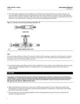
Instruction Manual 2. The control valve assembly may be installed in any orientation unless limited by seismic criteria. However, the normal method is with the actuator vertical above the valve. Other positions may result in uneven valve plug and cage wear and in improper operation. With some valves, the actuator may also need to be supported when it is not vertical. For more information, consult your Emerson Process Management sales office. Figure 2. Lubricator and Lubricator/Isolating Valve (Key 14) LUBRICATOR/ISOLATING VALVE Note If the valve being installed has a Whisper Trim cage with...
Open the catalog to page 4
Instruction Manual WARNING Personal injury could result from packing leakage. Valve packing was tightened before shipment; however, the packing might require some readjustment to meet specific service conditions. Check with your process or safety engineer for any additional measures that must be taken to protect against process media. Maintenance Valve parts are subject to normal wear and must be inspected and replaced as necessary. Inspection and maintenance frequency depends on the severity of service conditions. This section includes instructions for packing lubrication, packing...
Open the catalog to page 5
WARNING To avoid personal injury or property damage resulting from fire or explosion, do not lubricate packing used in oxygen service or in processes with temperatures over 260_C (500_F). If a lubricator or lubricator/isolating valve (figure 2) is provided for PTFE/composition or other packings that require lubrication, it will be installed in place of the 1/4 NPT pipe plug (key 14, figure 6). Use a silicon-base lubricant. Packing used in oxygen service or in processes with temperatures over 260C (500F) should not be lubricated. To operate the lubricator, turn the cap screw clockwise to...
Open the catalog to page 6
Instruction Manual Figure 3. PTFE V-Ring Packing Arrangements UPPER WIPER (KEY 12) PACKING FOLLOWER (KEY 13) FEMALE ADAPTOR PACKING RING FEMALE ADAPTOR PACKING RING MALE ADAPTOR MALE ADAPTOR FOR 316 OR 17-4PH SST METAL PACKING BOX PARTS LOWER WIPER LOWER WIPER FOR ALL OTHER METAL PACKING BOX PART MATERIALS SINGLE ARRANGEMENT UPPER WIPER (KEY 12) PACKING FOLLOWER (KEY 13) MALE ADAPTOR (KEY 31) PACKING RING (KEY 7) FEMALE ADAPTOR (KEY 32) LANTERN RING (KEY 8) ASSEMBLY 1 (POSITIVE PRESSURES) ASSEMBLY 3 (POSITIVE PRESSURES & VACUUM) DOUBLE ARRANGEMENT PACKING FOLLOWER (KEY 13) FEMALE ADAPTOR...
Open the catalog to page 7All FISHER REGULATORS catalogs and technical brochures
-
™ Control Valves and Instruments
16 Pages
-
Run with higher performing,
16 Pages
-
R Series
2 Pages
-
LP-Gas Technologies
118 Pages
-
Industrial Regulators
2 Pages
-
Type 92B Pressure Reducing Valve
16 Pages
-
Type 630R Relief Valve
8 Pages
-
Fisher™ 585C Piston Actuators
16 Pages
-
Type 630 Regulator
16 Pages
-
Fisher™ YD and YS Control Valves
24 Pages
-
easy-e Cryogenic Valves
12 Pages
-
Large ET and ED Valves
20 Pages
-
1305 Series Regulators
4 Pages
-
H200 Series Relief Valves
4 Pages
-
Air Application Map
1 Pages
-
DeltaV Controller Firewall
11 Pages
-
CSI 6500 Overview
12 Pages
-
The Criticality of Cooling
5 Pages
-
Ovation Security Center
4 Pages
-
DeltaV Smart Switches
28 Pages
-
Smartprocess™ Heater
5 Pages
-
FPSO Industry Solution
2 Pages
-
LP-31
96 Pages
-
CS 200 series
2 Pages
-
Regulators Mini Catalog
24 Pages
-
1301F, 1301G
12 Pages
-
MR95 and MR98
2 Pages
-
Fisher® D and DA Valves
12 Pages
-
Fisher® EZ easy-e Control Valve
40 Pages
-
Fisher® YD and YS Control Valves
24 Pages
-
Fisher® HPNS Control Valve
36 Pages
-
Fisher® HP Series Control Valves
28 Pages
-
Fisher® CAV4 Control Valve
28 Pages
-
Fisher® 377 Trip Valve
20 Pages
-
EZR Pressure Reducing Regulator
36 Pages
-
630 Regulator
16 Pages
-
627F Pressure Reducing Regulator
12 Pages
-
ACE97 Pad-Depad Valve
16 Pages
-
310A Pressure Reducing Regulator
16 Pages
-
S200 series
32 Pages
-
R622 series
8 Pages
-
Type HSR Pressure Regulators
20 Pages
-
cs200 series
40 Pages
-
CS400 Series
60 Pages
-
167D Series Switching Valves
8 Pages
Archived catalogs
-
Vapor Pressures of LP-Gas
1 Pages
-
Pipe and Tubing Sizing
1 Pages
-
Average Properties of LP-Gas
1 Pages
-
Pressure Equivalents
1 Pages


