
- Catalogs
- FISHER REGULATORS
- Fisher® EWD, EWS, and EWT Valves through NPS 12x8

Fisher® EWD, EWS, and EWT Valves through NPS 12x8

Fisher® EWD, EWS, and EWT Valves through NPS 12x8
This manual provides comprehensive guidance on the installation, maintenance, and parts for Fisher EWD, EWS, and EWT valves, emphasizing the necessity of proper training to prevent injury or damage.
Specifications
The valves are available with various end connection styles, such as flanged and buttwelding ends, and adhere to ASME standards for pressure and temperature ratings. Users must follow these specifications to ensure safety and optimal performance.
Description
The valves are single-port, globe-style with cage guiding and push-down-to-close valve plug action. They come in different configurations, including balanced and unbalanced valve plugs, with options for metal-to-metal or metal-to-PTFE seating. WhisperFlo cages are used for noise reduction in high-pressure applications.
Installation
Proper installation is crucial to avoid injury or equipment damage. The manual advises inspecting the valve and pipelines for damage, ensuring correct orientation, and using protective gear and appropriate hoisting equipment.
Maintenance
Regular maintenance is essential for proper valve function. The manual details procedures for packing lubrication, maintenance, and trim replacement, including retrofitting with C-seal trim.
Educational Services
Emerson Process Management offers training services for Fisher EW valves, with contact information provided for course enrollment.
Safety Warnings
The manual includes warnings about potential hazards like pressure release and packing leakage, advising consultation with safety engineers for additional measures.
Additional Information
Further specifications, including materials and valve plug travels, are available in the parts list section, along with guidance on ordering parts and using parts kits.
1. Support the actuator and bonnet during removal to prevent tipping.
2. During assembly, start with the plug/stem assembly in the bonnet, add gaskets and cage, and carefully raise the assembly into the valve body.
3. Torque the bonnet nuts and mount the actuator.
Maintenance Guidelines
1. Regular inspection and replacement of valve parts are necessary due to wear.
2. Follow safety precautions, such as wearing protective gear and ensuring the valve is not pressurized during maintenance.
3. Use lock-out procedures to maintain safety.
Packing Lubrication and Maintenance
1. Do not lubricate graphite packing; it is self-lubricating.
2. For PTFE/composition packings, use a silicon-based lubricant and follow specific procedures.
3. Inspect for leaks and tighten packing flange nuts if necessary.
Replacing Packing
1. Isolate the valve from pressure and drain process media.
2. Disconnect actuator and remove the bonnet carefully.
3. Inspect and clean packing box surfaces, replacing damaged parts if necessary.
4. Install new packing and reassemble using proper bolting procedures.
Safety Warnings
1. Ensure the valve is depressurized before maintenance.
2. Use approved materials for studs and nuts.
3. Follow proper tightening procedures to ensure seal integrity.
- Tighten packing flange nuts to the maximum recommended torque, then loosen and retighten to the minimum torque as per Table 6.
- For ENVIRO-SEAL or HIGH-SEAL live-loaded packing, refer to specific notes in the Packing Maintenance section.
- For other packing types, tighten nuts alternately in small increments until the flange is level and at a 90-degree angle to the valve stem.
- Mount the actuator on the valve assembly and reconnect according to the actuator instruction manual.
- Ensure the valve is not pressurized before maintenance.
- Wear protective gear and disconnect any operating lines.
- Use lock-out procedures to maintain safety measures.
- Table 5 provides body-to-bonnet bolt torque guidelines for various valve sizes.
- Table 6 specifies recommended torque for packing flange nuts based on valve stem diameter and pressure rating.
- Follow specific procedures for removing and replacing trim components.
- Inspect parts for wear or damage and replace as necessary.
- Use lapping compound for metal seats to improve shutoff.
- Carefully handle piston and seal rings to avoid damage.
- Follow procedures for replacing valve stems and adaptors.
- Install components according to specific construction diagrams and guidelines.
- Table 5: Body-to-Bonnet Bolt Torque Guidelines.
- Table 6: Recommended Torque for Packing Flange Nuts.
- Figures 22-29: Various construction details for EWD, EWS, EWT, Cavitrol III, Whisper Trim III, and WhisperFlo.
Specifications and Procedures:
1. Apply high-temperature lubricant to the plug threads and secure the C-seal retainer using a strap wrench.
2. Stake the threads on top of the plug to secure the retainer.
3. Replace piston rings as per the Trim Replacement section.
4. Reassemble the valve package ensuring the valve plug is seated with sufficient force to overcome C-seal resistance.
ENVIRO-SEAL Bellows Seal Bonnet Replacement:
1. Remove actuator and bonnet, discard old gaskets, and protect valve body opening.
2. Inspect and reuse the valve plug if in good condition; otherwise, replace it.
3. Attach the valve plug to the new ENVIRO-SEAL stem/bellows assembly without rotating the valve stem.
4. Install new gaskets and reassemble the bonnet.
Torque Specifications:
Refer to Table 8 for recommended torque values for packing flange nuts based on valve size and stem diameter.
Parts Ordering and Safety:
1. Use only genuine Fisher replacement parts to avoid warranty voidance and potential damage.
2. Ensure all parts are approved by Emerson/Fisher engineering.
Parts Kits:
1. Gasket Kits and Packing Kits are available for various valve sizes and configurations.
2. Retrofit Kits are available for converting to HIGH-SEAL or ENVIRO-SEAL packing box construction.
Warnings and Cautions:
1. Ensure proper installation of studs and nuts with visible manufacturer's markings.
2. Avoid using unapproved materials to prevent equipment damage and personal injury.
- Valve Components: The document lists key components such as cages, valve plug stems, seat rings, and C-seals, with specific part numbers and material specifications.
- Material Specifications: Materials like S20910, N07718, S41600, and S31600 are used for different components, with specific recommendations for high-temperature applications.
- Trim Types: Various trim types are discussed, including Cavitrol, Whisper, and standard trims, each with specific applications and configurations.
- Valve Assemblies: Detailed diagrams and descriptions of valve assemblies, including flow direction, port diameters, and optional features like drain plugs.
- Seal Rings: Information on two-piece and spring-loaded seal rings, including their orientation and application in different valve types.
- Spare Parts: The document highlights recommended spare parts for maintenance and repair.
- Temperature Limitations: Specific materials are not recommended for use above certain temperatures, such as CB7CU-1 cages above 210°C and R30006 cages above 427°C.
Catalog excerpts

Instruction Manual Fisherr EWD, EWS, and EWT Valves through NPS 12x8 Contents Introduction . . . . . . . . . . . . . . . . . . . . . . . . . . . . . . . . . . . 1 Scope of Manual . . . . . . . . . . . . . . . . . . . . . . . . . . . . . 1 Description . . . . . . . . . . . . . . . . . . . . . . . . . . . . . . . . . 3 Specifications . . . . . . . . . . . . . . . . . . . . . . . . . . . . . . . 3 Educational Services . . . . . . . . . . . . . . . . . . . . . . . . . 4 Installation . . . . . . . . . . . . . . . . . . . . . . . . . . . . . . . . . . . . 4 Inverted Globe Valve Applications (Actuator below valve) . . . . . . . . . . . . . . . . . . . . . 6 Maintenance . . . . . . . . . . . . . . . . . . . . . . . . . . . . . . . . . . 7 Packing Lubrication . . . . . . . . . . . . . . . . . . . . . . . . . . 8 Packing Maintenance . . . . . . . . . . . . . . . . . . . . . . . . 10 Replacing Packing . . . . . . . . . . . . . . . . . . . . . . . 11 Trim Maintenance . . . . . . . . . . . . . . . . . . . . . . . . . . 14 Trim Removal . . . . . . . . . . . . . . . . . . . . . . . . . . 15 Lapping Metal Seats . . . . . . . . . . . . . . . . . . . . . 16 Valve Plug Maintenance . . . . . . . . . . . . . . . . . . 17 Trim Replacement . . . . . . . . . . . . . . . . . . . . . . 19 Retrofit: Installing C-seal Trim . . . . . . . . . . . . . . . . 20 Replacement of Installed C-seal Trim . . . . . . . . . . . 24 Trim Removal (C-seal Constructions) . . . . . . . 24 Lapping Metal Seats (C-seal Constructions) . . 25 Remachining Metal Seats (C-seal Constructions) . . . . . . . . . . . . . . . . . 25 Trim Replacement (C-seal Constructions) . . . 26 ENVIRO-SEALt Bellows Seal Bonnet . . . . . . . . . . . 27 Parts Ordering . . . . . . . . . . . . . . . . . . . . . . . . . . . . . . . . 32 Parts Kits . . . . . . . . . . . . . . . . . . . . . . . . . . . . . . . . . . . . . 33 Parts List . . . . . . . . . . . . . . . . . . . . . . . . . . . . . . . . . . . . . 36 Figure 1. Fisher NPS 12x6 EW Series Valve With 667 Actuator Introduction Scope of Manual This instruction manual includes installation, maintenance, and parts information for Fisher NPS 4x2 through 12x8 EWD, EWS, and EWT valves (figure 1). Refer to separate manuals for instructions covering the actuator and accessories. Do not install, operate, or maintain an EW valve without being fully trained and qualified in valve, actuator, and accessory installation, operation, and maintenance. To avoid personal injury or property damage, it is important to carefully read, understand, and follow all the contents of this manual, including all safety cautions and warnings. If you have any questions about these instructions, contact your Emerson Process Management sales office before proceeding.
Open the catalog to page 1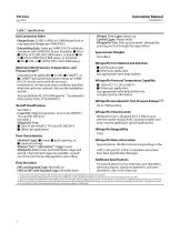
Instruction Manual Table 1. Specifications End Connection Styles Flanged Ends: CL300, CL600, or CL900 Raised-face or ring-type joint flanges per ASME B16.5 Buttwelding Ends: Styles per ASME B16.25 schedules consistent with ASME B16.34 are: Schedules J 40 or J 80 for all CL300 and CL600 valves, Schedule J 80 or J XXS for NPS 8x6 CL900 valves, or Schedule J 80, J 100, or J 120 for NPS 12x8 CL900 valves. Maximum Inlet Pressures, Temperatures, and Pressure Drops(1) Consistent with applicable J CL300, J CL600(2), or J CL900(3) pressure/temperature ratings per ASME B16.34, but do not exceed the pressure,...
Open the catalog to page 2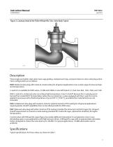
Instruction Manual Figure 2. Cutaway Detail of the Fisher WhisperFlo Trim, Valve Body Typical Description These single-port globe-style valves have cage guiding, clamped seat rings, and push-down-to-close valve plug action. Valve configurations are as follows: EWD: Balanced valve plug with metal-to-metal seating for all general applications over a wide range of pressure drops and temperatures. C-seal trim is available for EWD valves, CL300 and CL600, in sizes NPS 6x4x2-1/2, 6x4, 8x4, 8x6, 12x6, 10x8, and 12x8. With C-seal trim, a balanced valve can achieve high-temperature, Class V shutoff. Because...
Open the catalog to page 3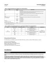
Instruction Manual Table 2. Shutoff Classification Per ANSI/FCI 70-2 and IEC 60534-4 Valve Shutoff Class II (standard) III (optional for NPS 6x4 through 12x6 valves with optional single graphite piston ring or for NPS 10x8 and 12x8 valves with optional double piston rings) IV (optional for NPS 6x4 through 12x8 valves with optional multiple graphite piston rings) EWT with all except Cavitrol III cages Standard Air Test (maximum leakage is 0.05 mL/min/psid/inch port diameter) IV (standard) V (optional, consult your Emerson Process Management sales office) EWT with 1-stage Cavitrol III cage EWT...
Open the catalog to page 4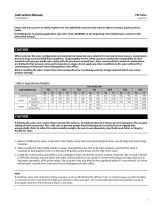
Instruction Manual Check with your process or safety engineer for any additional measures that must be taken to protect against process media. If installing into an existing application, also refer to the WARNING at the beginning of the Maintenance section in this instruction manual. CAUTION When ordered, the valve configuration and construction materials were selected to meet particular pressure, temperature, pressure drop and controlled fluid conditions. Responsibility for the safety of process media and compatibility of valve materials with process media rests solely with the purchaser and...
Open the catalog to page 5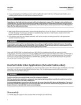
Instruction Manual 4. Use accepted piping and welding practices when installing the valve in the line. For flanged valve bodies, use a suitable gasket between the valve body and pipeline flanges. CAUTION Depending on valve body materials used, post weld heat treating may be required. If so, damage to internal elastomeric and plastic parts, as well as internal metal parts is possible. Shrink-fit pieces and threaded connections may also loosen. In general, if post weld heat treating is to be performed, remove all trim parts. Contact your Emerson Process Management sales office for additional information....
Open the catalog to page 6
2. Provide adequate support to the bonnet while removing the bonnet nuts. 3. Be aware that the bonnet/plug/cage may tip over as they are lowered from the valve body. Make provision to prevent tipping. 4. Be aware that the cage and seat ring may not come out with the bonnet and plug/stem assembly. If this occurs, make provision to support these parts, as they may fall out unexpectedly. Start this assembly procedure with the plug/stem assembly already installed in the bonnet. Put the gaskets and cage onto the bonnet and plug. Place the seat ring with the seat ring gasket onto the cage, if applicable...
Open the catalog to page 7All FISHER REGULATORS catalogs and technical brochures
 Fisher™ 8590 High-Performance
16 Pages
 bulletin-fisher-657-and-667
16 Pages
Archived catalogs
 167D Series Switching Valves
8 Pages
 CS400 Series
60 Pages
 cs200 series
40 Pages
 Type HSR Pressure Regulators
20 Pages
 R622 series
8 Pages
 S200 series
32 Pages
 310A Pressure Reducing Regulator
16 Pages
 ACE97 Pad-Depad Valve
16 Pages
 627F Pressure Reducing Regulator
12 Pages
 630 Regulator
16 Pages
 EZR Pressure Reducing Regulator
36 Pages
 Fisher® 377 Trip Valve
20 Pages
 Fisher® CAV4 Control Valve
28 Pages
 Fisher® HP Series Control Valves
28 Pages
 Fisher® HPNS Control Valve
36 Pages
 Fisher® YD and YS Control Valves
24 Pages
 Fisher® EZ easy-e Control Valve
40 Pages
 Fisher® D and DA Valves
12 Pages
 MR95 and MR98
2 Pages
 1301F, 1301G
12 Pages
 Regulators Mini Catalog
24 Pages
 CS 200 series
2 Pages
 LP-31
LP-3196 Pages
 FPSO Industry Solution
2 Pages
 Smartprocess™ Heater
5 Pages
 DeltaV Smart Switches
28 Pages
 Ovation Security Center
4 Pages
 The Criticality of Cooling
5 Pages
 CSI 6500 Overview
12 Pages
 DeltaV Controller Firewall
11 Pages
 Air Application Map
1 Page
 H200 Series Relief Valves
4 Pages
 1305 Series Regulators
4 Pages
 Large ET and ED Valves
20 Pages
 easy-e Cryogenic Valves
12 Pages
 Fisher™ YD and YS Control Valves
24 Pages
 Type 630 Regulator
16 Pages
 Fisher™ 585C Piston Actuators
16 Pages
 Type 630R Relief Valve
8 Pages
 Type 92B Pressure Reducing Valve
16 Pages
 Industrial Regulators
2 Pages
 LP-Gas Technologies
118 Pages
 R Series
2 Pages
 Run with higher performing,
16 Pages
 ™ Control Valves and Instruments
16 Pages
 Pressure Equivalents
1 Page
 Pipe and Tubing Sizing
1 Page


- Manual valve
- FISHER control valve
- FISHER stainless steel valve
- Ball valve
- FISHER pneumatic valve
- Threaded valve
- Regulating valve
- Flange valve
- On/off valve
- Electric valve
- ISO valve
- Pressure gauge
- Level limit switch
- FISHER pressure regulator
- Gas valve
- Valve with handwheel
- FISHER pneumatically-operated valve
- Liquid level detector
- Butterfly valve