Catalog excerpts

Product Bulletin Fisherr DMA, DMA-AF, DMA-AF-HTC, DSA, and DVI Desuperheaters Fisher DMA, DMA-AF, DMA-AF-HTC, DSA, and DVI desuperheaters can be used in many applications to efficiently reduce the temperature of superheated steam to the desired set point. Available variations are mechanically atomized (both fixed geometry and variable geometry) and steam assisted. Desuperheaters are available for installation in steam lines from DN25 through DN1500 (NPS 1 through 60) in diameter and are capable of maintaining steam temperatures to within 6_C (10_F) of saturation temperatures. W6298 Available Insertion Style Desuperheaters DMA–A simple mechanically atomized desuperheater with single or multiple, fixed-geometry spray nozzles is intended for applications with nearly constant load. The DMA is installed through a flanged connection on the side of a DN150 (NPS 6) or larger pipeline. Maximum unit Cv is 3.8. DMA-AF–A variable-geometry, mechanically atomized, back-pressure-activated desuperheater with one, two, or three spray nozzles is designed for applications requiring control over moderate load fluctuations. The DMA-AF desuperheater (figure 1) is installed through a flanged connection on the side of a DN200 (NPS 8) or larger pipeline. Maximum unit Cv is 15.0.
Open the catalog to page 1
Product Bulletin DMA-AF-HTC– The DMA-AF-HTC is functionally equivalent to the DMA-AF, however it is structurally suited for severe applications. The most common applications include boiler interstage attemperation, where the desuperheater is exposed to high thermal cycling and stress, high steam velocities and flow induced vibration. In addition to this specific application, the DMA-AF-HTC is suitable for other severe desuperheating application environments. The DMA-AF-HTC uses a construction optimized to move weld joints away from high stress regions. The desuperheater design incorporates...
Open the catalog to page 2
Product Bulletin Specifications Available Types J DMA, J DMA-AF, J DMA-AF-HTC, J DSA, and J DVI (see the Available Desuperheater Types section for descriptions) Connections See table 1 Maximum Pressure Rating(1) Consistent with applicable pressure-temperature ratings (as shown in table 1) per ASME B16.34 Inherent Rangeability Up to 50:1. The ratio of maximum to minimum controllable Cv is dependent upon the available water pressure differential Spray Water Pressure Required(2) 3.5 to 35 bar (50 to 500 psi) greater than steam line pressure Atomizing Steam (Design DSA) Atomizing steam should...
Open the catalog to page 3
Product Bulletin 85.2:DMA July 2014 temperature is controlled by varying the amount of spraywater flow. For the most efficient use of heat energy from steam, it is necessary to reduce the temperature of steam to near the saturation temperature. With steam that is at or near the saturation temperature, it is possible to recover the large amount of energy that was put into the steam when it was heated from water to steam. Desuperheating, or attemperation as it is sometimes called, is most often used to •improve thermal efficiency of heat transfer processes by using steam near saturation, •...
Open the catalog to page 4
Product Bulletin Figure 1. Fisher DMA-AF Desuperheater Figure 3. Fisher DMA-AF-HTC Desuperheater Figure 2. Fisher DSA Desuperheater Figure 4. Fisher DVI Desuperheater
Open the catalog to page 5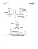
Product Bulletin Figure 5. Typical Installation FISHER 667-EZ SPRAYWATER CONTROL VALVE FISHER 667-EZ ATOMIZING STEAM ISOLATION VALVE SPRAYWATER ATOMIZING STEAM FISHER DSA DESUPERHEATER STEAMFLOW FISHER SPRAYWATER CONTROL VALVE FISHER DMA DESUPERHEATER STEAMFLOW DMA, DMA-AF, OR DMA-AF-HTC DESUPERHEATER
Open the catalog to page 6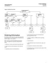
Product Bulletin Figure 6. Selection Flow Chart YES REQUIRED TURNDOWN GREATER THAN 25:1 REQUIRED TURNDOWN GREATER THAN 20:1 PIPELINE SIZE GREATER THAN NPS 6 YES STEAM PRESSURE REDUCTION REQUIRED PIPELINE SIZE GREATER THAN NPS 6 PIPELINE SIZE GREATER THAN NPS 6 ATOMIZING STEAM AVAILABLE REQUIRED TURNDOWN GREATER THAN 5:1 Ordering Information 4. Atomizing steam pressure and temperature (DSA desuperheater only). Use the flow chart in figure 6 to select the appropriate desuperheater for your requirements. Dimensions are shown in figures 7, 8, 9, and 10. 5. Design conditions, if different from...
Open the catalog to page 7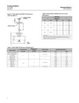
Product Bulletin Table 2. Fisher DMA and DMA-AF Face-to-Face Dimensions Figure 7. Fisher DMA and DMA-AF Dimensions (also see table 2) ASME RF FLANGE (WATER) D (Nominal Pipe Size), NPS 1. DMA only. Note: For NPS 6 and 8 (DMA-AF only) mounting flange, add 69.6 mm (2.75 inches) to the A and T dimensions. For CL2500 mounting, consult your Emerson Process Management sales office. Refer to the certified drawing to verify the inside-diameter requirements of mounting for DMA-AF. Table 3. Fisher DMA-AF Minimum Mounting I.D. VALVE BODY PIPE MINIMUM BODY FLANGE WATER FLANGE NOZZLE MODEL DMA-AF-H...
Open the catalog to page 8
Product Bulletin Figure 8. Fisher DSA Dimensions (also see table 4) 254 (10.00) ASME RF FLANGE (STEAM) ASME RF FLANGE (WATER) 508 (20.00) Table 4. Fisher DSA Dimensions DIMENSION A mm D (Nominal Pipe Size), NPS Note: For NPS 6 mounting flange, add 69.6 mm (2.75 inches) to the A and T dimensions. For CL2500 mounting, consult your Emerson Process Management sales office.
Open the catalog to page 9
Product Bulletin Figure 9. Fisher DVI Dimensions (also see table 5) ASME RAISED-FACE FLANGE (WATER) ASME RAISED-FACE FLANGE 250 RMS SERRATED SURFACE FLOW DIRECTION INSTALLATION CONFIGURATION (2 GASKETS REQUIRED) Table 5. Fisher DVI Dimensions NOMINAL PIPE SIZE, NPS C–WATER CONNECTION TO MATING FLANGE A PRESSURE RATING
Open the catalog to page 10
Product Bulletin Figure 10. Fisher DMA-AF-HTC Dimensions (also see tables 6 and 7) MOUNTING FLANGE (SAME SIZE & PRESSURE RATING AS BODY FLANGE) E AVAILABLE NOZZLE CONFIGURATIONS GA32864-C Table 6. Fisher DMA-AF-HTC Dimensions DESUPERHEATER BODY FLANGE(1) Pressure Rating Pressure Rating WATER FLANGE Size, NPS 1. The NPS 4 DMA-AF-HTC requires a 4.00 inch minimum mounting I.D. Contact your Emerson Process Management sales office for NPS 3 DMA-AF-HTC minimum mounting I.D. Table 7. Fisher DMA-AF-HTC Installation Dimensions DIMENSION D (Nominal Pipe Size) Desuperheater Body Flange Size, NPS
Open the catalog to page 11All FISHER REGULATORS catalogs and technical brochures
-
™ Control Valves and Instruments
16 Pages
-
Run with higher performing,
16 Pages
-
R Series
2 Pages
-
LP-Gas Technologies
118 Pages
-
Industrial Regulators
2 Pages
-
Type 92B Pressure Reducing Valve
16 Pages
-
Type 630R Relief Valve
8 Pages
-
Fisher™ 585C Piston Actuators
16 Pages
-
Type 630 Regulator
16 Pages
-
Fisher™ YD and YS Control Valves
24 Pages
-
easy-e Cryogenic Valves
12 Pages
-
Large ET and ED Valves
20 Pages
-
1305 Series Regulators
4 Pages
-
H200 Series Relief Valves
4 Pages
-
Air Application Map
1 Pages
-
DeltaV Controller Firewall
11 Pages
-
CSI 6500 Overview
12 Pages
-
The Criticality of Cooling
5 Pages
-
Ovation Security Center
4 Pages
-
DeltaV Smart Switches
28 Pages
-
Smartprocess™ Heater
5 Pages
-
FPSO Industry Solution
2 Pages
-
LP-31
96 Pages
-
CS 200 series
2 Pages
-
Regulators Mini Catalog
24 Pages
-
1301F, 1301G
12 Pages
-
MR95 and MR98
2 Pages
-
Fisher® D and DA Valves
12 Pages
-
Fisher® EZ easy-e Control Valve
40 Pages
-
Fisher® YD and YS Control Valves
24 Pages
-
Fisher® HPNS Control Valve
36 Pages
-
Fisher® HP Series Control Valves
28 Pages
-
Fisher® CAV4 Control Valve
28 Pages
-
Fisher® 377 Trip Valve
20 Pages
-
EZR Pressure Reducing Regulator
36 Pages
-
630 Regulator
16 Pages
-
627F Pressure Reducing Regulator
12 Pages
-
ACE97 Pad-Depad Valve
16 Pages
-
310A Pressure Reducing Regulator
16 Pages
-
S200 series
32 Pages
-
R622 series
8 Pages
-
Type HSR Pressure Regulators
20 Pages
-
cs200 series
40 Pages
-
CS400 Series
60 Pages
-
167D Series Switching Valves
8 Pages
Archived catalogs
-
Vapor Pressures of LP-Gas
1 Pages
-
Pipe and Tubing Sizing
1 Pages
-
Average Properties of LP-Gas
1 Pages
-
Pressure Equivalents
1 Pages


