- Catalogs
- FISHER REGULATORS
- Fisher® D and DA Valves
Fisher® D and DA Valves
1 /12Pages

Fisher® D and DA Valves
1 /12Pages
Catalog excerpts
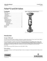
Instruction Manual Fisherr D and DA Valves Contents Figure 1. Fisher D Valve with 657 Actuator Introduction . . . . . . . . . . . . . . . . . . . . . . . . . . . . . . . . . 1 Scope of Manual . . . . . . . . . . . . . . . . . . . . . . . . . . . . . 1 Description . . . . . . . . . . . . . . . . . . . . . . . . . . . . . . . . . 1 Specifications . . . . . . . . . . . . . . . . . . . . . . . . . . . . . . . 2 Educational Services . . . . . . . . . . . . . . . . . . . . . . . . . 2 Ceramic Trim . . . . . . . . . . . . . . . . . . . . . . . . . . . . . . . . 3 Installation . . . . . . . . . . . . . . . . . . . . . . . . . . . . . . . . . . 3 Maintenance . . . . . . . . . . . . . . . . . . . . . . . . . . . . . . . . . 5 Packing Lubrication . . . . . . . . . . . . . . . . . . . . . . . . . . 5 Packing Maintenance . . . . . . . . . . . . . . . . . . . . . . . . . 6 Replacing Packing . . . . . . . . . . . . . . . . . . . . . . . . . . . 6 Trim Maintenance . . . . . . . . . . . . . . . . . . . . . . . . . . . 8 Disassembly . . . . . . . . . . . . . . . . . . . . . . . . . . . . . 8 Lapping Metal Seats . . . . . . . . . . . . . . . . . . . . . . 8 Assembly . . . . . . . . . . . . . . . . . . . . . . . . . . . . . . . 9 Parts Ordering . . . . . . . . . . . . . . . . . . . . . . . . . . . . . . . . 9 Parts Kits . . . . . . . . . . . . . . . . . . . . . . . . . . . . . . . . . . . 10 Parts List . . . . . . . . . . . . . . . . . . . . . . . . . . . . . . . . . . . 10 Introduction Scope of Manual This instruction manual includes installation, maintenance, and parts information for Fisher D and DA valves. Refer to separate manuals for instructions covering the actuator, positioner, and accessories. Do not install, operate, or maintain a D or DA valve without being fully trained and qualified in valve, actuator, and accessory installation, operation, and maintenance. To avoid personal injury or property damage, it is important to carefully read, understand, and follow all the contents of this manual, including all safety cautions and warnings. If you have any questions about these instructions, contact your Emerson Process Management sales office before proceeding. Unless otherwise noted, all NACE references are to NACE MR0175-2002. Description The D globe-style (figure 1) and DA angle-style (figure 5) valves are single-port, metal-seated valves for high-pressure applications.
Open the catalog to page 1
Instruction Manual Table 1. Specifications Maximum Inlet Pressures and Temperatures(1) Maximum Service Temperature If the valve nameplate shows an ASME pressure-temperature class, maximum inlet pressure and temperature is consistent with applicable ASME class per ASME B16.34. If the nameplate does not show an ASME class, it will show a maximum cold working pressure at 38_C (100_F) (for example, 3600, 6000, 9000, or 10,000 psi) 232_C (450_F) Flow Characteristic Equal Percentage Flow Direction Maximum Allowable Pressure Drops(1) D Valve: Flow up through the seat ring and out past the valve plug...
Open the catalog to page 2
Instruction Manual Ceramic Trim Some types of ceramic trim, including the VTC (very tough ceramic) variety, can create a spark under certain circumstances. When the edge of a ceramic part is struck against a second ceramic part with enough force, a spark can be created. WARNING Avoid personal injury and property damage from ignition of process fluid caused by sparks from ceramic trim. Do not use ceramic trim where the process fluid is unstable or if it is an explosive mixture (such as ether and air). Installation WARNING Always wear protective gloves, clothing, and eyewear when performing any...
Open the catalog to page 3
Instruction Manual CAUTION Depending on valve body materials used, post-weld heat treating might be needed. If so, damage to internal elastomeric and plastic parts, as well as internal metal parts is possible. Shrink-fit pieces and threaded connections may also loosen. In general, if post-weld heat treating is needed, remove all trim parts. Contact your Emerson Process Management sales office for additional information. For screwed end connections, apply pipe compound to pipeline threads. 4. To allow continuous operation during inspection or maintenance, install a three-valve bypass around the...
Open the catalog to page 4
Instruction Manual Maintenance WARNING Avoid personal injury from sudden release of process pressure. Before performing any maintenance operations: D Do not remove the actuator from the valve while the valve is still pressurized. D Always wear protective gloves, clothing, and eyewear when performing any maintenance operations to avoid personal injury. D Disconnect any operating lines providing air pressure, electric power, or a control signal to the actuator. Be sure the actuator cannot suddenly open or close the valve. D Use bypass valves or completely shut off the process to isolate the valve...
Open the catalog to page 5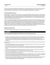
lubricant. Do not lubricate packing used in oxygen service. To operate the lubricator, turn the cap screw clockwise to force the lubricant into the packing box. The lubricator/isolating valve operates the same way except open the isolating valve before turning the cap screw. Close the isolating valve after lubrication is completed. Packing Maintenance Refer to figures 3, 4, and 5 for key number locations. For spring-loaded single PTFE V-ring packing, the packing spring (key 9) maintains a sealing force on the packing. If you find leakage around the packing follower (key 10), check to be sure...
Open the catalog to page 6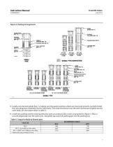
Instruction Manual Figure 3. Packing Arrangements UPPER WIPER MALE ADAPTOR LANTERN RING ASSEMBLY 1 ASSEMBLY 2 ASSEMBLY 3 ASSEMBLY 1 ASSEMBLY 2 ASSEMBLY 3 (POSITIVE (VACUUM) (POSITIVE (POSITIVE (VACUUM) (POSITIVE PRESSURES) PRESSURES PRESSURES) PRESSURES & VACUUM) & VACUUM) FEMALE ADAPTOR LANTERN RING DOUBLE PTFE 8. Install a new bonnet gasket (key 7), making sure the gasket seating surfaces are clean and smooth. Carefully install the valve plug/stem assembly into the valve body. Then slide the bonnet over the stem and thread it tightly into the valve body, per the torque values in table 4. 9....
Open the catalog to page 7All FISHER REGULATORS catalogs and technical brochures
 ™ Control Valves and Instruments
16 Pages
 Run with higher performing,
16 Pages
 R Series
2 Pages
 LP-Gas Technologies
118 Pages
 Industrial Regulators
2 Pages
 Type 92B Pressure Reducing Valve
16 Pages
 Type 630R Relief Valve
8 Pages
 Fisher™ 585C Piston Actuators
16 Pages
 Type 630 Regulator
16 Pages
 Fisher™ YD and YS Control Valves
24 Pages
 easy-e Cryogenic Valves
12 Pages
 Large ET and ED Valves
20 Pages
 1305 Series Regulators
4 Pages
 H200 Series Relief Valves
4 Pages
 Air Application Map
1 Page
 DeltaV Controller Firewall
11 Pages
 CSI 6500 Overview
12 Pages
 The Criticality of Cooling
5 Pages
 Ovation Security Center
4 Pages
 DeltaV Smart Switches
28 Pages
 Smartprocess™ Heater
5 Pages
 FPSO Industry Solution
2 Pages
 LP-31
LP-3196 Pages
 CS 200 series
2 Pages
 Regulators Mini Catalog
24 Pages
 1301F, 1301G
12 Pages
 MR95 and MR98
2 Pages
 Fisher® EZ easy-e Control Valve
40 Pages
 Fisher® YD and YS Control Valves
24 Pages
 Fisher® HPNS Control Valve
36 Pages
 Fisher® HP Series Control Valves
28 Pages
 Fisher® CAV4 Control Valve
28 Pages
 Fisher® 377 Trip Valve
20 Pages
 EZR Pressure Reducing Regulator
36 Pages
 630 Regulator
16 Pages
 627F Pressure Reducing Regulator
12 Pages
 ACE97 Pad-Depad Valve
16 Pages
 310A Pressure Reducing Regulator
16 Pages
 S200 series
32 Pages
 R622 series
8 Pages
 Type HSR Pressure Regulators
20 Pages
 cs200 series
40 Pages
 CS400 Series
60 Pages
 167D Series Switching Valves
8 Pages


Archived catalogs
 Pressure Equivalents
1 Page
 Pipe and Tubing Sizing
1 Page


- SARRALLE manual valve
- SARRALLE control valve
- SARRALLE stainless steel valve
- SARRALLE ball valve
- SARRALLE pneumatic valve
- Threaded valve
- SARRALLE regulating valve
- Flange valve
- SARRALLE shut-off valve
- SARRALLE electric valve
- ISO valve
- Level limit switch
- Pressure gauge
- SARRALLE pressure regulator
- SARRALLE gas valve
- Valve with handwheel
- Liquid level detector
- SARRALLE pneumatically-operated valve
- SARRALLE level sensor