Catalog excerpts

Product Bulletin Fisherr C1 Pneumatic Controllers and Transmitters Fisher C1 controllers and transmitters continue the tradition of durable and dependable Fisher pressure instrumentation while addressing air/gas consumption concerns. The C1 is used wherever durable and dependable pressure instrumentation is required. The use of this product in demanding applications, such as those found in chemical process, gas, and oil production industries, demonstrates its versatility. The C1 can reduce steady-state air/gas consumption to as little as 1/10th that of previous products. C1 controllers compare sensed process pressure (or differential pressure) with an operator-adjusted set point, and send a pneumatic signal to an adjacent control element that maintains the process pressure at or near the set point value. C1 transmitters sense process variables and send out a pneumatic signal, usually to an indicating or recording device that directly indicates the process measurement. Unless otherwise noted, all NACE references are to NACE MR0175 / ISO15156 & NACE MR0103. FISHER C1 PNEUMATIC CONTROLLER YOKE-MOUNTED ON CONTROL VALVE ACTUATOR n Sour Service Capability—Materials are available for Features n Wide Range of Sensing Elements—A Bourdon tube is available for high pressures or bellows for vacuum and low pressures. Either kind of sensing element can be installed in the case with the controller or transmitter. Two interchangeable ranges of output bellows and gauges also are available. n Reduced Air/Gas Consumption—The C1 pneumatic controller is an energy efficient choice, helping to improve profits and uptime. Steady-state consumption rate is less than the 6 scfh requirement set for the oil and gas industry by the US Environmental Protection Agency (New Source Performance Standards Subpart OOOO, EPA‐HQ‐QAR‐2010-0505). applications handling sour process fluids. These constructions comply with the metallurgical requirements of NACE MR0175 / ISO15156 & NACE MR0103. Environmental restrictions may apply. n Mounting Versatility—Install the case on a panel, wall or pipestand, as well as directly on the control valve actuator. n Reduced Maintenance Costs—A spring-out cleaning wire, shown in figure 4, provides for in-service cleaning of the relay orifice. n Proportional-Only, Proportional-Plus-Reset, and Differential Gap Configurable—The C1 controller can be configured to provide various modes of control. (Features continued on page 3)
Open the catalog to page 1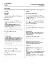
Product Bulletin Specifications Supply and Output Pressure Gauge Ranges Available Configurations See table 1 Input Signal Proportional Band Adjustment For Proportional-Only Controllers: Full output pressure change adjustable from J 2% to 100% of the sensing element range for 0.2 to 1.0 bar (3 to 15 psig) or J 4% to 100% of the sensing element range for 0.4 to 2.0 bar (6 to 30 psig) Type: J Gauge pressure, J vacuum, J compound pressure, or J differential pressure of a liquid or gas Limits: See table 2 or 3 Output Signal For Proportional-Plus-Reset Controllers: Full output pressure change...
Open the catalog to page 2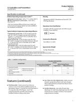
Product Bulletin Specifications (continued) Ambient Operating Temperature Limits(1) J Standard Construction: -40 to 71_C (-40 to 160_F) J High Temperature Construction: -18 to 104_C (0 to 220_F) Anti-reset windup (differential pressure relief) and process pressure gauge options are only available in the standard construction Designed to NEMA 3 (Weatherproof) and IEC 529 IP54 Specifications Hazardous Area Classification Typical Ambient Temperature Operating Influence Proportional Control only: ±3.0% of output span for each 28_C (50_F) change in temperature between -40 and 71_C (-40 and...
Open the catalog to page 3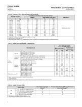
Product Bulletin Table 2. Bourdon Tube Pressure Ranges and Materials MAXIMUM ALLOWABLE STATIC PRESSURE LIMITS(2) With Optional Travel Stop(3) 1. Range marked on Bourdon tube may be in kPa (1 bar = 100 kPa). 2. Bourdon tube may be pressured to limit shown without permanent zero shift. 3. With travel stop set at 110% of the range. 4. Bourdon tubes are also available in NACE compliant material. Contact your Emerson Process Management sales office for additional information. Table 3. Bellows Pressure Ranges and Materials MAXIMUM ALLOWABLE STATIC PRESSURE LIMITS(1) Stainless Steel Brass...
Open the catalog to page 4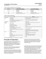
Product Bulletin Table 5. Supply and Output Pressure Gauge Ranges 0.2 to 1.0 Bar (3 to 15 Psig) or 0 and 1.4 Bar (0 and 20 Psig) Output Gauge Scale 0.4 to 2.0 Bar (6 to 30 Psig) or 0 and 2.4 Bar (0 and 35 Psig) Output Table 6. Construction Materials Part Sensing bellows Brass or stainless steel Stainless steel or NACE compliant stainless steel(1) Stainless steel or NACE compliant stainless steel(1) All other interior tubing Stainless steel Exterior tubing Copper (with or without PVC plastic lining), stainless steel, or synthetic rubber Exterior fittings Brass or stainless steel Nozzle and...
Open the catalog to page 5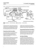
Product Bulletin Figure 1. Schematic of Reverse-Acting Proportional-Only and Proportional-Plus-Reset Controllers CONSTANT SUPPLY PRESSURE INLET END OF RELAY VALVE SMALL DIAPHRAGM LARGE DIAPHRAGM RESTRICTION EXHAUST EXHAUST END OF RELAY BOURDON TUBE FIXED PIVOT RESET BELLOWS RESET BELLOWS PROPORTIONAL BAND ADJUSTMENT KNOB TO FINAL CONTROL ELEMENT PRESSURE-SETTING KNOB PRESSURE SETTING DIAL VENT BEAM AND FLAPPER CANTILEVER SPRING PROPORTIONAL BELLOWS PROPORTIONAL BELLOWS RESET VALVE SENSED PRESSURE PROPORTIONAL-PLUS-RESET CONTROLLER PROPORTIONAL-ONLY CONTROLLER SENSED PRESSURE OUTPUT PRESSURE...
Open the catalog to page 6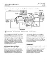
Product Bulletin Figure 2. Schematic of Reverse-Acting Proportional-Plus-Reset Controller with Anti-Reset Windup CONSTANT SUPPLY PRESSURE DIFFERENTIAL RELIEF VALVE PRESSURE-SETTING KNOB PRESSURE SETTING DIAL RESET BELLOWS PROPORTIONAL BAND ADJUSTMENT KNOB TO FINAL CONTROL ELEMENT CANTILEVER SPRING PROPORTIONAL BELLOWS RESET VALVE SENSED PRESSURE SENSED PRESSURE OUTPUT PRESSURE NOZZLE PRESSURE RESET PRESSURE controller output pressure causes the relay to rapidly exhaust loading pressure from the control element, and also from the proportional system and spring side of the relief diaphragm....
Open the catalog to page 7All FISHER REGULATORS catalogs and technical brochures
-
™ Control Valves and Instruments
16 Pages
-
Run with higher performing,
16 Pages
-
R Series
2 Pages
-
LP-Gas Technologies
118 Pages
-
Industrial Regulators
2 Pages
-
Type 92B Pressure Reducing Valve
16 Pages
-
Type 630R Relief Valve
8 Pages
-
Fisher™ 585C Piston Actuators
16 Pages
-
Type 630 Regulator
16 Pages
-
Fisher™ YD and YS Control Valves
24 Pages
-
easy-e Cryogenic Valves
12 Pages
-
Large ET and ED Valves
20 Pages
-
1305 Series Regulators
4 Pages
-
H200 Series Relief Valves
4 Pages
-
Air Application Map
1 Pages
-
DeltaV Controller Firewall
11 Pages
-
CSI 6500 Overview
12 Pages
-
The Criticality of Cooling
5 Pages
-
Ovation Security Center
4 Pages
-
DeltaV Smart Switches
28 Pages
-
Smartprocess™ Heater
5 Pages
-
FPSO Industry Solution
2 Pages
-
LP-31
96 Pages
-
CS 200 series
2 Pages
-
Regulators Mini Catalog
24 Pages
-
1301F, 1301G
12 Pages
-
MR95 and MR98
2 Pages
-
Fisher® D and DA Valves
12 Pages
-
Fisher® EZ easy-e Control Valve
40 Pages
-
Fisher® YD and YS Control Valves
24 Pages
-
Fisher® HPNS Control Valve
36 Pages
-
Fisher® HP Series Control Valves
28 Pages
-
Fisher® CAV4 Control Valve
28 Pages
-
Fisher® 377 Trip Valve
20 Pages
-
EZR Pressure Reducing Regulator
36 Pages
-
630 Regulator
16 Pages
-
627F Pressure Reducing Regulator
12 Pages
-
ACE97 Pad-Depad Valve
16 Pages
-
310A Pressure Reducing Regulator
16 Pages
-
S200 series
32 Pages
-
R622 series
8 Pages
-
Type HSR Pressure Regulators
20 Pages
-
cs200 series
40 Pages
-
CS400 Series
60 Pages
-
167D Series Switching Valves
8 Pages
Archived catalogs
-
Vapor Pressures of LP-Gas
1 Pages
-
Pipe and Tubing Sizing
1 Pages
-
Average Properties of LP-Gas
1 Pages
-
Pressure Equivalents
1 Pages


