
- Catalogs
- FISHER REGULATORS
- Fisher™ 8590 High-Performance

Fisher™ 8590 High-Performance
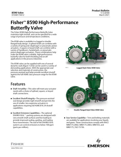
Fisher™ 8590 High-Performance
- Shaft Versatility: Offers multiple shaft connection options including splined, square, or keyed to accommodate different actuator requirements.
- Shutoff Integrity: Features a pressure-assisted seal design for tight shutoff, allowing the use of smaller actuators.
- Emissions Capabilities: Optional ENVIRO-SEAL packing systems reduce emissions to below 100 ppm.
- Sour Service Capability: Complies with NACE standards for handling sour liquids and gases.
- Fire Safe Construction: Fire tested according to API 607 standards with Phoenix III seal.
- Bidirectional Shutoff: Consistent torque is required to open and close the valve, regardless of pressure direction.
- Easy Installation: Self-centering body design facilitates quick and accurate installation.
- Valve Body Size: NPS 3 to 24
- Pressure Rating: CL600 per ASME B16.34
- Materials: Includes WCC, CF8M, LCC, CD3MN, M35-2, CW2M
- Seal Types: Options include Soft Seal, Metal Seal, Phoenix III Seal, and High-Pressure Seal
- Temperature Range: Up to 538°C (1000°F) depending on material
Catalog excerpts
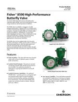
Product Bulletin Fisher™ 8590 High-Performance Butterfly Valve The Fisher 8590 High-Performance Butterfly Valve maintains tight shutoff, and can be specified for a wide range of pressure and temperature conditions. The 8590 valve is available in a lugged or double flanged body design. A splined shaft can combine with a variety of spring-and- diaphragm or pneumatic piston actuators. A square or keyed shaft can combine with a variety of handlevers, handwheels, or pneumatic piston diaphragm actuators. These combinations help make the 8590 valve a reliable, high-performance butterfly valve for both throttling and on-off applications in the process industries. The 8590 valve can be supplied with one of several dynamic seals (figure 1) that can be used in a variety of demanding applications. With the appropriate seal selection and materials of construction, the pressure-assisted seal helps provide excellent shutoff against the full ASME class pressure range for the 8590 valve. Lugged Style Fisher 8590 Valve Shaft Versatility— This valve will meet your actuator needs with a choice of splined, square, or keyed shaft connections. Excellent Shutoff Integrity—The pressure-assisted seal design provides tight shutoff and permits the use of smaller, less expensive actuators in applications requiring full ASME B16.34 shutoff capabilities. X1610 Excellent Emissions Capabilities— The optional ENVIRO-SEALt packing systems are designed with very smooth shaft surfaces and live-loading to provide improved sealing, guiding, and loading force transmission. The seal of the ENVIRO-SEAL system can control emissions to below 100 ppm (parts per million). Double Flanged Style Fisher 8590 Valve Sour Service Capability— Trim and bolting materials are available for applications involving sour liquids and gases. These constructions comply with NACE MR0175-2002, MR0175-2003, MR0103, and MR0175 / ISO
Open the catalog to page 1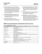
Product Bulletin 51.6:8590 March 2021 ■ Fire Safe Construction — The 8590 valve has been fire tested per API 607, 6th edition with the Phoenix III seal. Standard construction requires 316 stainless steel chrome plated disk, graphite packing, metal bearings and S17400 H1025 SST or S20910 SST shaft. For information on fire tested valves, consult Fire-Tested Status of Fisher Rotary Valves Bulletin 59.3:025 (D103907X012). ■ Reliable Flange Gasketing Surface—Seal retainer screws are located so there is no interference with the sealing function of either flat sheet or spiral wound line flange gaskets....
Open the catalog to page 2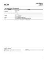
Product Bulletin Table 2. Materials (Other Valve Components) COMPONENT Anti-Blowout Ring (NPS 3-8 only) Seal Ring Metal: S21800 Phoenix III: S20910/ETFE HPS: S21800 nitrided PEEK, S31600 Nitrided, R30006 (Alloy 6) PTFE/carbon-filled PTFE (standard), graphite die-molded ribbon, ENVIRO-SEAL PTFE packing, ENVIRO-SEAL graphite packing Table of Contents Features . . . . . . . . . . . . . . . . . . . . . . . . . . . . . . . . . . . . . 1 Specifications . . . . . . . . . . . . . . . . . . . . . . . . . . . . . . . . 2 Standard Seal Configurations . . . . . . . . . . . . . . . . . . . 4 Installation...
Open the catalog to page 3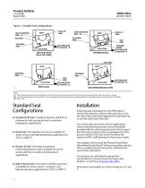
Product Bulletin Figure 1. Available Seal Configurations ANTI-EXTRUSION RING 3 BACK-UP RING BACK-UP RING RETAINING RING SEAL RING RETAINING RING VALVE DISK HIGH PRESSURE AT SHUTOFF 2 SEAL RING VALVE DISK SOFT SEAL WITH BACK-UP O-RING RESILIENT INSERT HIGH PRESSURE AT SHUTOFF 2 SEAL RING BODY RETAINING RING RETAINING RING SEAL RING VALVE DISK HIGH PRESSURE AT SHUTOFF 1 METAL SEAL VALVE DISK HIGH PRESSURE AT SHUTOFF 1 Notes: This unidirectional seal must be installed so that the retaining ring is downstream from the high pressure side of the valve at shutoff, as shown. 1 2 For this bidirectional...
Open the catalog to page 4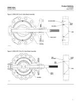
Product Bulletin Figure 2. 8590, NPS 3 to 8, Valve Body Assembly SEAL RETAINER VALVE BODY SEAL RING DRIVE SHAFT Figure 3. 8590, NPS 10 to 24, Valve Body Assembly SEAL RETAINER VALVE BODY SEAL RING DRIVE SHAFT BEARING
Open the catalog to page 5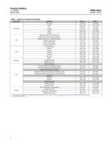
Product Bulletin51.6:8590 March 2021 Table 3. Material Temperature Ranges 1. The maximum temperature for a standard design of the 8590 valve is 538°C (1000°F). Contact your Emerson sales office for use in higher temperature applications. 2. For use with soft seal only.
Open the catalog to page 6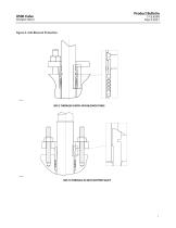
Product Bulletin Figure 4. Anti-Blowout Protection NPS 3 THROUGH 8 WITH ANTI-BLOWOUT RING NPS 10 THROUGH 24 WITH STEPPED SHAFT
Open the catalog to page 7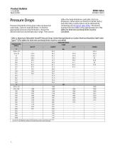
Product Bulletin 51.6:8590 March 2021 Pressure drop limits of any given valve are based on valve body, and trim material limits. To find the appropriate pressure drop limitation, choose the desired valve size and temperature range. Then search table 4 for body limitations and table 5 for trim limitations. Information on limits for CW2M, M35-2, and other alloy constructions can be obtained by contacting your Emerson sales office. The lowest number from the tables is the appropriate limit. The tables for both trim and body limits must be consulted. Table 4. Maximum Allowable Shutoff Pressure Drops...
Open the catalog to page 8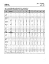
Product Bulletin51.6:8590 March 2021 Table 5. Maximum Allowable Shutoff Pressure Drops based on Trim(1) Note: Do not exceed the ASME pressure/temperature ratings of the valve or mating flanges. 1. Trim ratings based on S17400 H1025 shaft. For other shaft materials,please contact factory. 2. The temperature limit of S17400 H1025 shaft material is 427°C (800°F). For higher temperatures another shaft material option must be selected.
Open the catalog to page 9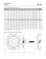
Product Bulletin51.6:8590 March 2021 Table 6. Single Flange Dimensions and Weights 1. This is the nominal valve shaft diameter to be used when selecting Fisher actuators. 2. Threaded hole per ASME B1.1.
Open the catalog to page 10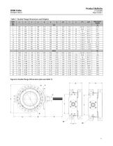
Product Bulletin51.6:8590 March 2021 Table 7. Double Flange Dimensions and Weights
Open the catalog to page 11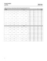
Product Bulletin51.6:8590 March 2021 Table 8. Dimensions, Optional Square Shaft and Mounting Bracket (ISO 5211)
Open the catalog to page 12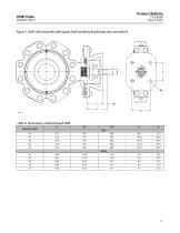
Product Bulletin Figure 7. 8590 Valve Assembly with Square Shaft and Mounting Bracket (also see table 8) Table 9. Dimensions, Optional Keyed Shaft Valve Size, NPS
Open the catalog to page 13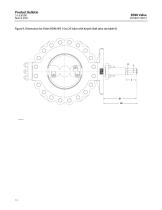
Product Bulletin Figure 9. Dimensions for Fisher 8590 NPS 14 to 24 Valve with Keyed Shaft (also see table 9)
Open the catalog to page 14All FISHER REGULATORS catalogs and technical brochures
 bulletin-fisher-657-and-667
16 Pages
Archived catalogs
 167D Series Switching Valves
8 Pages
 CS400 Series
60 Pages
 cs200 series
40 Pages
 Type HSR Pressure Regulators
20 Pages
 R622 series
8 Pages
 S200 series
32 Pages
 310A Pressure Reducing Regulator
16 Pages
 ACE97 Pad-Depad Valve
16 Pages
 627F Pressure Reducing Regulator
12 Pages
 630 Regulator
16 Pages
 EZR Pressure Reducing Regulator
36 Pages
 Fisher® 377 Trip Valve
20 Pages
 Fisher® CAV4 Control Valve
28 Pages
 Fisher® HP Series Control Valves
28 Pages
 Fisher® HPNS Control Valve
36 Pages
 Fisher® YD and YS Control Valves
24 Pages
 Fisher® EZ easy-e Control Valve
40 Pages
 Fisher® D and DA Valves
12 Pages
 MR95 and MR98
2 Pages
 1301F, 1301G
12 Pages
 Regulators Mini Catalog
24 Pages
 CS 200 series
2 Pages
 LP-31
LP-3196 Pages
 FPSO Industry Solution
2 Pages
 Smartprocess™ Heater
5 Pages
 DeltaV Smart Switches
28 Pages
 Ovation Security Center
4 Pages
 The Criticality of Cooling
5 Pages
 CSI 6500 Overview
12 Pages
 DeltaV Controller Firewall
11 Pages
 Air Application Map
1 Page
 H200 Series Relief Valves
4 Pages
 1305 Series Regulators
4 Pages
 Large ET and ED Valves
20 Pages
 easy-e Cryogenic Valves
12 Pages
 Fisher™ YD and YS Control Valves
24 Pages
 Type 630 Regulator
16 Pages
 Fisher™ 585C Piston Actuators
16 Pages
 Type 630R Relief Valve
8 Pages
 Type 92B Pressure Reducing Valve
16 Pages
 Industrial Regulators
2 Pages
 LP-Gas Technologies
118 Pages
 R Series
2 Pages
 Run with higher performing,
16 Pages
 ™ Control Valves and Instruments
16 Pages
 Pressure Equivalents
1 Page
 Pipe and Tubing Sizing
1 Page


- Manual valve
- FISHER control valve
- FISHER stainless steel valve
- Ball valve
- FISHER pneumatic valve
- Threaded valve
- Regulating valve
- Flange valve
- On/off valve
- Electric valve
- ISO valve
- Pressure gauge
- Level limit switch
- FISHER pressure regulator
- Gas valve
- Valve with handwheel
- FISHER pneumatically-operated valve
- Liquid level detector