Catalog excerpts

Product Bulletin Fisher™ 4660 High-Low Pressure Pilot The Fisher 4660 pneumatic high-low pressure pilot activates safety shutdown systems for flowlines, production vessels, and compressors. This pilot is available with either single or dual set point capability, using switch points to maintain full output pressure when the process pressure is within the set point range. If the process pressure is outside this range, the pilot switches from full output pressure to zero output pressure. The primary switching mechanism in this pilot is a block-and-bleed relay assembly. This construction can be used in both block-and-bleed and bleed-only systems. Unless otherwise noted, all NACE references are to NACE MR0175-2002. FISHER 4660 HIGH-LOW PRESSURE PILOT WITH BLOCK AND BLEED RELAY Features n Safety Certification—The 4660 is certified for use in Safety Instrumented System (SIS) applications. Certification is by exida Consulting LLC, a global provider of functional safety and control system security (see figure 1). SIS certification is identified on the product by a label affixed to the case. The functional safety assessment was performed to the requirements of IEC 61508: ed2, 2010, SIL3 for mechanical components. n Superior Performance—Repeatability meets the U.S. Minerals Management Service test tolerances referenced in Outer Continental Shelf (OCS) Order No. 5 and defined in the American Petroleum Institute (API) RP14C standard. n Cost-Effective Design—One pilot provides either a high-low function or a single switch point, whichever the application requires.
Open the catalog to page 1
Product Bulletin n NACE Conformance—A NACE compliant Bourdon Figure 2. Fisher 4660 High-Low Pressure Pilot with Block and Bleed Relay; Left Side with Case Cover Off tube is available for those applications where the pilot must meet the requirements of NACE MR0175-2002. n Environmental Packaging—Construction materials have been selected to protect the pilot from corrosive environments such as the salt spray atmosphere of offshore platforms. n Reliable Operation—The pilot uses a field-proven Bourdon tube process pressure sensing element, shown in figure 2, that reduces maintenance by...
Open the catalog to page 2
Product Bulletin Specifications Construction Materials Available Configurations J High-low, J low-only, or J high-only set point capability Case and Cover: Polyester Front Cover: Tinted polycarbonate with scratch-resistant coating Base: Hard-anodized nickel-sealed aluminum alloy Bourdon Tube: J S31600 SST or J NACE compliant material Relay Body, Relay Flange, Nozzle/Flapper Assembly Orifice Block, and Switch Point Housings: Glass-filled polyphenylene sulfide Relay Diaphragm: Fluorosilicone/Polyester Relay Discs: Fluorosilicone Process Pressure Block, Tubing, Front Plate, Flapper, Linkages,...
Open the catalog to page 3
Product Bulletin Specifications (continued) Hazardous Area Classification Safety Instrumented System Classification Complies with the requirements of ATEX Group II Category 2 Gas and Dust SIL3 capable certified by exida Consulting LLC Ex h IIC Tx Gb Ex h IIIC Tx Db Approximate Weight Maximum surface temperature (Tx) depends on operating conditions Meets Customs Union technical regulation TP TC 012/2011 for Groups II/III Category 2 equipment II Gb c T*X III Db c T*X J Visual output indication J stainless steel panel mounting flange, J set point indication, and J tamper-resistant front cover...
Open the catalog to page 4
Product Bulletin Table 3. Maximum Allowable Process Pressure(1) BOURDON TUBE RATING Bar(2) MAXIMUM ALLOWABLE EMERGENCY PROCESS PRESSURE Stainless Steel Bourdon Tubes NACE Compliant Bourdon Tubes Maximum Allowable Process Pressure to Ensure Set Point Readjustability(3) 13.8 34.8 51.7 103.5 155.1 172.4 517.2 646.3 N/A 1. Normal operating process pressures should not exceed the Bourdon tube rating. 2. Ratings indicated on Bourdon tube are in psig and kPa (1 bar = 100 kPa). 3. Values listed for the NACE compliant Bourdon tubes are for a 2% deviation from set point due to overpressure.
Open the catalog to page 5
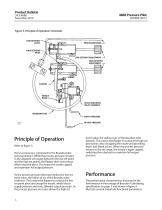
Product Bulletin Figure 3. Principle of Operation Schematic PROCESS PRESSURE HIGH SETPOINT PIVOT LOW SETPOINT ADJUSTMENT HIGH SETPOINT ADJUSTMENT SPRING FLAPPER NOZZLE BEAM BLOCK AND BLEED RELAY ASSEMBLY BOURDON TUBE SUPPLY PRESSURE 38A3803-A A2898-2 Principle of Operation Refer to figure 3. Process pressure is connected to the Bourdon tube sensing element. While the process pressure remains in the adjusted set ranges (between the low set point and the high set point), the flapper does not contact either set point pivot. This keeps the nozzle capped and maintains full output pressure. As...
Open the catalog to page 6
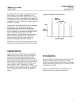
Product Bulletin D200051X012 SL represents the low set point and SH represents the high set point. The set range capability is 3 to 97 percent of the Bourdon tube rating. However, with a single high-low unit or a high-only/low-only pair, there is a limit on how close to each other the set points can be adjusted. This limit is defined as set point ΔPMIN and is shown as SL′ and SH′. Figure 4. Performance Characteristics TRIP-TORESET ZONE SET POINT ΔPMIN 100% Trip-to-reset is the combined effect of pilot deadband and hysteresis. After the pilot has tripped, it automatically resets when the...
Open the catalog to page 7
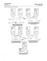
Product Bulletin Figure 5. Typical Connection Schematics OUTPUT OUTPUT A. HIGH-ONLY AND LOW-ONLY PILOTS SENSING A SINGLE PROCESS POINT AND HAVING A SINGLE OUTPUT B. LOW-ONLY AND HIGH/LOW PILOTS WITH DUAL OUTPUTS AND DIFFERENT PROCESS PRESSURES OUTPUT TO SUPPLY OUTPUT C. LOW-ONLY AND HIGH/LOW PILOTS WITH SINGLE OUTPUT AND DIFFERENT PROCESS PRESSURES D. LOW-ONLY AND HIGH-ONLY PILOTS WITH DUAL OUTPUTS AND COMMON PROCESS PRESSURE 38A6086-B ELECTRICAL PRESSURE SWITCH SUPPLY OUTPUT 39A1578-A E. HIGH/LOW PILOT INTERFACED WITH A PRESSURE SWITCH
Open the catalog to page 8
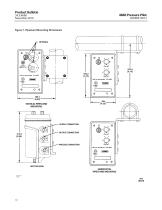
Product Bulletin Figure 6. Panel Mounting Dimensions 130 (5.12) FIELD MOUNTING PANEL MOUNTING RIGHT SIDE VIEW FRONT REMOVAL mm (INCH)
Open the catalog to page 9
Product Bulletin Figure 7. Pipestand Mounting Dimensions VERTICAL PIPESTAND MOUNTING SUPPLY CONNECTION OUTPUT CONNECTION PROCESS CONNECTION BOTTOM VIEW HORIZONTAL PIPESTAND MOUNTING 10B2287-B B1965
Open the catalog to page 10All FISHER REGULATORS catalogs and technical brochures
-
™ Control Valves and Instruments
16 Pages
-
Run with higher performing,
16 Pages
-
R Series
2 Pages
-
LP-Gas Technologies
118 Pages
-
Industrial Regulators
2 Pages
-
Type 92B Pressure Reducing Valve
16 Pages
-
Type 630R Relief Valve
8 Pages
-
Fisher™ 585C Piston Actuators
16 Pages
-
Type 630 Regulator
16 Pages
-
Fisher™ YD and YS Control Valves
24 Pages
-
easy-e Cryogenic Valves
12 Pages
-
Large ET and ED Valves
20 Pages
-
1305 Series Regulators
4 Pages
-
H200 Series Relief Valves
4 Pages
-
Air Application Map
1 Pages
-
DeltaV Controller Firewall
11 Pages
-
CSI 6500 Overview
12 Pages
-
The Criticality of Cooling
5 Pages
-
Ovation Security Center
4 Pages
-
DeltaV Smart Switches
28 Pages
-
Smartprocess™ Heater
5 Pages
-
FPSO Industry Solution
2 Pages
-
LP-31
96 Pages
-
CS 200 series
2 Pages
-
Regulators Mini Catalog
24 Pages
-
1301F, 1301G
12 Pages
-
MR95 and MR98
2 Pages
-
Fisher® D and DA Valves
12 Pages
-
Fisher® EZ easy-e Control Valve
40 Pages
-
Fisher® YD and YS Control Valves
24 Pages
-
Fisher® HPNS Control Valve
36 Pages
-
Fisher® HP Series Control Valves
28 Pages
-
Fisher® CAV4 Control Valve
28 Pages
-
Fisher® 377 Trip Valve
20 Pages
-
EZR Pressure Reducing Regulator
36 Pages
-
630 Regulator
16 Pages
-
627F Pressure Reducing Regulator
12 Pages
-
ACE97 Pad-Depad Valve
16 Pages
-
310A Pressure Reducing Regulator
16 Pages
-
S200 series
32 Pages
-
R622 series
8 Pages
-
Type HSR Pressure Regulators
20 Pages
-
cs200 series
40 Pages
-
CS400 Series
60 Pages
-
167D Series Switching Valves
8 Pages
Archived catalogs
-
Vapor Pressures of LP-Gas
1 Pages
-
Pipe and Tubing Sizing
1 Pages
-
Average Properties of LP-Gas
1 Pages
-
Pressure Equivalents
1 Pages


