Catalog excerpts

Product Bulletin Fisherr 4200 Electronic Position Transmitters The instrument can sense the position of rotary or sliding‐stem valves, vents, dampers or other devices. When the instrument is mounted, a potentiometer shaft is mechanically connected to the device to sense mechanical motion. For a standard instrument, a single potentiometer is provided for position input or an optional dual element potentiometer is available to allow independent electrical operation of the transmitter and alarm circuits. The instrument has standard, or long‐stroke (see figure 3), capabilities for sliding‐stem actuator applications. For long‐stroke applications, a multi‐turn potentiometer attached to a travel transducer assembly is used to sense linear motion of the actuator stem or other devices. The instrument with standard capabilities can also be used on quarter‐turn actuators. For instruments equipped with electronic travel limit alarms, individual electronic high and low alarm circuits drive separate high and low alarm SPDT relays. The user adjusts the trip point and deadband of the high and low alarms to the desired travel limits. When the sense potentiometer voltage is higher than the high trip point, the electronic high alarm circuit de‐energizes the high alarm relay. When the sense potentiometer voltage is lower than the low trip point, the low alarm circuit de‐energizes the low alarm relay. The low trip point may be offset from the high trip point by as little as 5% of the remaining span. In the event of a power loss to the alarm circuits, both alarms are tripped (both relays are de‐energized). This indicates a system failure because the actuator cannot be physically at both travel limits simultaneously. The relay contacts are isolated from the transmitter and alarm circuits. FISHER 4200 TRANSMITTER ON A CONTROL VALVE
Open the catalog to page 1
Product Bulletin Specifications Operating Influences Available Configurations Ambient Temperature: For a 56_C (100_F) change in normal operating conditions, maximum zero shift is ±0.5%, and the maximum span shift is ±0.75% of span Power Supply: Output signal changes less than ±0.1% when operating terminal voltage varies between 11 and 30 volts DC See table 1 Input Signal Source J Standard single potentiometer, or optional J dual potentiometer is the source for the transmitter and travel limit alarm circuit inputs. Refer to table 2 for zero and span limits. Electromagnetic Compatibility for...
Open the catalog to page 2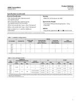
Product Bulletin Specifications (continued) Electrical Classification CSA—Intrinsically Safe, Explosion-proof, Dust‐Ignition proof FM—Intrinsically Safe, Explosion-proof, Dust‐Ignition proof, Non‐Incendive ATEX—Intrinsically Safe, Type n, Dust, Flameproof IECEx—Intrinsically Safe, Type n, Dust, Flameproof Refer to tables 5, 6, 7, and 8 for additional information. Housing NEMA 4X; CSA Enclosure 4X; IP66 Approximate Weight Transmitter Without Mounting Bracket: 1.8 kg (4 pounds) Options Long‐stroke applications: J 12 or J 24 inch travel NOTE: Specialized instrument terms are defined in...
Open the catalog to page 3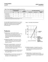
Product Bulletin Table 3. Power Supply Requirements and Wiring Connections TRANSMITTER TERMINAL VOLTAGE (VDC) FIELD WIRING CONNECTIONS Transmitter Only Transmitter with Travel Limit Alarms Travel Limit Alarms without Transmitter X indicates this connection required. 1. Supply wire provides power supply positive connection for electronic circuits and relay coils (in instruments with travel limit alarms). 2. Signal wire provides connection for device receiving 4 to 20 mA transmitter signal. 3. Relay return wire provides separate return wire for relay coil currents. Features n High Accuracy—A...
Open the catalog to page 4
Product Bulletin Figure 2. Fisher 4210 Transmitter Details PRINTED WIRING BOARD FIELD PRINTED WIRING BOARD TERMINAL BLOCK NUMBER 3 TERMINAL BLOCK NUMBER 1 TERMINAL BLOCK NUMBER 1 TERMINAL BLOCK NUMBER 2 TRANSMITTER COMPARTMENT n Easy Maintenance—The simple design of the transmitter and alarms allows easy maintenance. The high reliability of the instrument requires minimum spare parts inventory. n Moisture Resistant—The field wiring compartment is isolated from the electronic compartment. This protects the electronic circuits from any moisture brought into the housing via the field wiring...
Open the catalog to page 5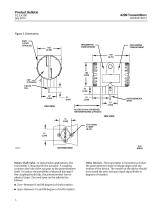
Product Bulletin Figure 3. Dimensions PORT 1/2 NPT (2 PLACES) TRANSMITTER COMPARTMENT FIELD WIRING COMPARTMENT POTENTIOMETER SHAFT ALLOW 254 mm (10 INCHES) FOR MAINTENANCE (2 PLACES) BOTTOM VIEW Rotary‐Shaft Valve—In typical valve applications, the transmitter is mounted on the actuator. A coupling connects the hub of the actuator to the potentiometer shaft. To reduce the possibility of physical damage if the coupling should slip, the potentiometer has no physical stops. Zero and span can be adjusted as follows: n Zero—Between 0 and 90 degrees of shaft rotation. n Span—Between 15 and 90...
Open the catalog to page 6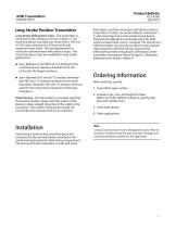
Product Bulletin Long‐Stroke Position Transmitter Long‐Stroke Sliding‐Stem Valve—The transmitter is mounted on the actuator as shown in figure 3. The travel transducer assembly can sense from a 105 mm (4.125 inch) minimum to a 610 mm (24 inch) maximum stem travel. The sensing element is a multi‐turn potentiometer with physical stops. Two travel transducer sizes are available for long stroke applications. limit alarms, and the instrument with alarms only (no transmitter circuits), use terminal blocks numbered 1, 2, and 3 (see figure 2) on the printed wiring board. These terminal blocks are...
Open the catalog to page 7
Product Bulletin Figure 4. Mounting Dimensions ACTUATOR HOUSING TYPICAL MOUNTING BRACKET DIMENSIONS FOR SLIDING‐STEM ACTUATORS TYPICAL MOUNTING BRACKET DIMENSIONS FOR ROTARY‐SHAFT ACTUATORS FISHER 4200 TRANSMITTER MOUNTING MOUNTING BRACKET DIMENSIONS FOR FISHER 585CLS ACTUATORS WITH A 152 mm (6‐INCH) CHANNEL Note: 1 For other sizes of 585CLS actuators, the mounting plate length will change depending on the channel width.
Open the catalog to page 8
Product Bulletin Table 4. Fisher 4211 and 4221 Electronic Position Transmitter EMC Summary Results—Immunity Port Basic Standard Test Level Electrostatic Discharge (ESD) Enclosure 80 to 1000 MHz @ 10V/m with 1 kHz AM at 80% 1400 to 2000 MHz @ 3V/m with 1 kHz AM at 80% 2000 to 2700 MHz @ 1V/m with 1 kHz AM at 80% 1 kV (line to ground only, each) Rated power frequency magnetic field Burst (fast transients) I/O signal/control Specification limit = ±1% of span 1. A = No degradation during testing. B = Temporary degradation during testing, but is self‐recovering. Table 5. Hazardous Area...
Open the catalog to page 9All FISHER REGULATORS catalogs and technical brochures
-
™ Control Valves and Instruments
16 Pages
-
Run with higher performing,
16 Pages
-
R Series
2 Pages
-
LP-Gas Technologies
118 Pages
-
Industrial Regulators
2 Pages
-
Type 92B Pressure Reducing Valve
16 Pages
-
Type 630R Relief Valve
8 Pages
-
Fisher™ 585C Piston Actuators
16 Pages
-
Type 630 Regulator
16 Pages
-
Fisher™ YD and YS Control Valves
24 Pages
-
easy-e Cryogenic Valves
12 Pages
-
Large ET and ED Valves
20 Pages
-
1305 Series Regulators
4 Pages
-
H200 Series Relief Valves
4 Pages
-
Air Application Map
1 Pages
-
DeltaV Controller Firewall
11 Pages
-
CSI 6500 Overview
12 Pages
-
The Criticality of Cooling
5 Pages
-
Ovation Security Center
4 Pages
-
DeltaV Smart Switches
28 Pages
-
Smartprocess™ Heater
5 Pages
-
FPSO Industry Solution
2 Pages
-
LP-31
96 Pages
-
CS 200 series
2 Pages
-
Regulators Mini Catalog
24 Pages
-
1301F, 1301G
12 Pages
-
MR95 and MR98
2 Pages
-
Fisher® D and DA Valves
12 Pages
-
Fisher® EZ easy-e Control Valve
40 Pages
-
Fisher® YD and YS Control Valves
24 Pages
-
Fisher® HPNS Control Valve
36 Pages
-
Fisher® HP Series Control Valves
28 Pages
-
Fisher® CAV4 Control Valve
28 Pages
-
Fisher® 377 Trip Valve
20 Pages
-
EZR Pressure Reducing Regulator
36 Pages
-
630 Regulator
16 Pages
-
627F Pressure Reducing Regulator
12 Pages
-
ACE97 Pad-Depad Valve
16 Pages
-
310A Pressure Reducing Regulator
16 Pages
-
S200 series
32 Pages
-
R622 series
8 Pages
-
Type HSR Pressure Regulators
20 Pages
-
cs200 series
40 Pages
-
CS400 Series
60 Pages
-
167D Series Switching Valves
8 Pages
Archived catalogs
-
Vapor Pressures of LP-Gas
1 Pages
-
Pipe and Tubing Sizing
1 Pages
-
Average Properties of LP-Gas
1 Pages
-
Pressure Equivalents
1 Pages


