- Catalogs
- FISHER REGULATORS
- Fisher™ 249 Sensor, Level Controller, andTransmitter Dimensions
Fisher™ 249 Sensor, Level Controller, andTransmitter Dimensions
1 /8Pages

Fisher™ 249 Sensor, Level Controller, andTransmitter Dimensions
1 /8Pages
Catalog excerpts

Product Bulletin Fisher™ 1052 Size 70 Diaphragm Rotary Actuator Fisher 1052 size 70 spring‐return diaphragm rotary actuators operate splined shaft rotary valves, such as 8580, 8532, 8590, CV500, V500, and Vee‐Ballt (V150, V200 and V300) valves. 1052 actuators are suitable for on‐off service or for throttling service. This actuator is designed for easy installation of a broad range of options: limit switches, position indicating switches, positioners, and manual over‐rides. Option applicability varies with actuator size. Refer to the specifications table and table 4 for information concerning option applicability and specifications. Features n Application Flexibility-- 1052 rotary actuators are available with fail‐open or fail‐close construction and can be mounted in any of four actuator‐valve mounting positions. See figure 5 for mounting positions. These actuators can be mounted on a broad range of Fisher valves or used with other equipment. Typical Fisher 1052 Actuator with Vee‐Ball Valve and FIELDVUE™ DVC6200 Digital Valve Controller n Minimal Dead Band-- Single joint linkage with splined and clamped lever minimizes lost motion and improves control accuracy. n Long Service Life-- Rugged construction provides stability, corrosion resistance, and protection from deformation should over‐pressurization occur. n Safety-- The 1052 actuator has an externally accessible spring adjuster to relieve spring compression (see figure 1). Actuator‐valve linkage is completely enclosed, yet the valve packing adjustment remains accessible without remov
Open the catalog to page 1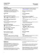
Product Bulletin Specifications Available Configurations For on‐off service without a positioner or for throttling services with or without a positioner Direct Acting: Increasing loading pressure extends the diaphragm rod out of the spring barrel piping. If stroking time is critical, consult your Emerson sales office or Local Business Partner Diaphragm Casing Displacement See table 1 Construction Materials Standard Diaphragm Pressure Ranges J 0 to 2.3 bar (0 to 33 psig), J 0 to 2.8 bar (0 to 40 psig), and J 0 to 3.8 bar (0 to 55 psig) Maximum Diaphragm Sizing Pressure(1) 3.8 bar (55 psig) Maximum...
Open the catalog to page 2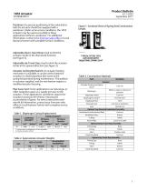
Product Bulletin D104082X012 Positioner: For precise positioning of the valve disk or ball, the actuator should be equipped with a positioner. Under some service conditions, the 1052 actuator may be used successfully in these applications without a positioner. For additional information, contact your Emerson sales office or Local Business Partner with complete service conditions. Adjustable Down‐Travel Stop: Used to limit the actuator stroke in the downward direction (see figure 3). Figure 1. Sectional Views of Spring Seat Construction Details TYPICAL OF THE 1052 ACTUATOR WITH ADJUSTABLE SPRING...
Open the catalog to page 3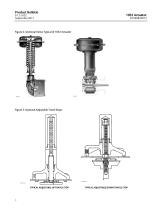
Product Bulletin Figure 2. Sectional Views Typical of 1052 Actuator Figure 3. Optional Adjustable Travel Stops TYPICAL ADJUSTABLE UP TRAVEL STOP TYPICAL ADJUSTABLE DOWN TRAVEL
Open the catalog to page 4
Product Bulletin Table 4. Construction Features and Option Applicability STANDARD TRAVEL STOP ACTUATOR SIZE ACTUATOR TYPE Style OPTIONAL TRAVEL STOP Top‐mounted up‐travel stop or down‐travel stop OPTIONAL MANUAL OVERRIDE ACCESSORY SWITCH MOUNTING Mechanically Operated Switches Top‐mounted handwheel for infrequent operation or side‐mounted manual actuator for routine operation Externally mounted, lever operated Figure 4. Top‐Mounted Handwheel
Open the catalog to page 5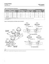
Product Bulletin Table 5. Mounting Styles and Positions VALVE SERIES OR DESIGN MOUNTING PDTC PDTO BALL/PLUG ROTATION TO CLOSE CCW(3) CCW PDTC PDTO PDTC PDTO VALVE SERIES OR DESIGN DISK/BALL ROTATION TO CLOSE CW CW 1. PDTC—Push‐down‐to‐close, and PDTO—Push‐down‐to‐open. 2. A left hand ball will be required for NPS 3 through 12 V150, V200 and V300, Series B and NPS 14 through 20, with or without an attenuator. 3. CCW = counterclockwise 4. CW = clockwise Figure 5. Mounting Styles and Positions (also see table 5) STYLE A STYLE D FLOW STYLE C LEFT‐HAND MOUNTING RIGHT‐HAND MOUNTING STYLE C Notes: 1...
Open the catalog to page 6
Product Bulletin Figure 6. Dimensions (also see tables 6, 7 and 8) TOP‐MOUNTED HANDWHEEL ACTUATOR/VALVE BODY MOUNTING DIMENSIONS 1/2‐14 NPT SIZE 70 Installation The actuator is normally positioned vertically in a horizontal pipeline. Four mounting styles and four positions for each style are possible (see figure 5). Due to its weight, the 1052 size 70 actuator must be externally supported if mounted in the horizontal position. When looking in the direction of flow in the pipeline, an actuator is right‐hand mounted when it is on the right side of the pipeline, and an actuator is left‐hand mounted...
Open the catalog to page 7
Product Bulletin Adjustable Travel Stops Figure 7. Actuator Locking Mechanism Adjustable travel stops (in addition to those shown in figure 3) are available as discussed below. ACTUATOR LEVER As used here, down or downward means in a direction toward the valve shaft and away from the piston and diaphragm. MODIFIED ACTUATOR HOUSING An adjustable down travel stop is installed in a special actuator housing. The assembly consists of a special housing, cap screw, locknut, lever, and rod end bearing. The cap screw can be positioned to limit downward travel of the actuator lever to any rotation between...
Open the catalog to page 8All FISHER REGULATORS catalogs and technical brochures
 ™ Control Valves and Instruments
16 Pages
 Run with higher performing,
16 Pages
 R Series
2 Pages
 LP-Gas Technologies
118 Pages
 Industrial Regulators
2 Pages
 Type 92B Pressure Reducing Valve
16 Pages
 Type 630R Relief Valve
8 Pages
 Fisher™ 585C Piston Actuators
16 Pages
 Type 630 Regulator
16 Pages
 Fisher™ YD and YS Control Valves
24 Pages
 easy-e Cryogenic Valves
12 Pages
 Large ET and ED Valves
20 Pages
 1305 Series Regulators
4 Pages
 H200 Series Relief Valves
4 Pages
 Air Application Map
1 Page
 DeltaV Controller Firewall
11 Pages
 CSI 6500 Overview
12 Pages
 The Criticality of Cooling
5 Pages
 Ovation Security Center
4 Pages
 DeltaV Smart Switches
28 Pages
 Smartprocess™ Heater
5 Pages
 FPSO Industry Solution
2 Pages
 LP-31
LP-3196 Pages
 CS 200 series
2 Pages
 Regulators Mini Catalog
24 Pages
 1301F, 1301G
12 Pages
 MR95 and MR98
2 Pages
 Fisher® D and DA Valves
12 Pages
 Fisher® EZ easy-e Control Valve
40 Pages
 Fisher® YD and YS Control Valves
24 Pages
 Fisher® HPNS Control Valve
36 Pages
 Fisher® HP Series Control Valves
28 Pages
 Fisher® CAV4 Control Valve
28 Pages
 Fisher® 377 Trip Valve
20 Pages
 EZR Pressure Reducing Regulator
36 Pages
 630 Regulator
16 Pages
 627F Pressure Reducing Regulator
12 Pages
 ACE97 Pad-Depad Valve
16 Pages
 310A Pressure Reducing Regulator
16 Pages
 S200 series
32 Pages
 R622 series
8 Pages
 Type HSR Pressure Regulators
20 Pages
 cs200 series
40 Pages
 CS400 Series
60 Pages
 167D Series Switching Valves
8 Pages


Archived catalogs
 Pressure Equivalents
1 Page
 Pipe and Tubing Sizing
1 Page


- SARRALLE manual valve
- SARRALLE control valve
- SARRALLE stainless steel valve
- SARRALLE pneumatic valve
- Threaded valve
- SARRALLE regulating valve
- Flange valve
- SARRALLE shut-off valve
- SARRALLE electric valve
- ISO valve
- Level limit switch
- Pressure gauge
- SARRALLE pressure regulator
- SARRALLE gas valve
- Valve with handwheel
- Liquid level detector
- SARRALLE pneumatically-operated valve
- SARRALLE level sensor