
- Catalogs
- FISHER REGULATORS
- bulletin-fisher-657-and-667

bulletin-fisher-657-and-667
bulletin-fisher-657-and-667
- Application Versatility: Available in five types and eleven sizes, with options for spring rates, travel stops, and manual operators.
- Linearity and Stability: Molded diaphragms provide excellent linearity and dynamic stability, with reduced response time.
- High Thrust and Durability: Constructed with thick-walled cast iron and steel for stability and corrosion resistance.
- Cold Service Applications: Performance down to -50°C, with positioners recommended below -40°C.
- Positive Connections: Split block stem connection ensures solid motion transfer and easy mounting.
- Operating Pressure Range: 0.2 to 1.0 bar or 0.4 to 2.0 bar, with model variations.
- Temperature Range: Standard operation from -40 to 82°C, with optional silicone diaphragms up to 149°C.
- Construction Materials: Diaphragm casings made from steel, cast iron, or aluminum, with diaphragms of nitrile or silicone.
- Direct Action (657): Air pressure moves the actuator stem downward, providing fail-open or fail-closed actions.
- Reverse Action (667): Air pressure moves the actuator stem upward, with fail-closed or fail-open actions.
- Handwheels: Used for manual valve positioning, available in top-mounted and side-mounted configurations.
- Adjustable Travel Stops: Limit travel in specified directions, with various styles for different actuator types.
- Other Accessories: Includes transducers, positioners, air relays, and volume boosters.
Catalog excerpts
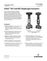
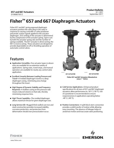
Product Bulletin 61.1:657 September 2017 Fisher 657 and 667 spring-opposed diaphragm actuators position the valve plug in the valve in response to varying controller or valve positioner pneumatic output signals applied to the actuator diaphragm. Zero setting of the actuator is determined by the compression of the actuator spring. Span is set by both the actuator spring rate and the number of springs available. The 657 actuator is direct-acting; the 667 is reverse-acting. These actuators are designed to provide dependable on-off or throttling operation of automatic control valves. ■ Application Versatility—Five actuator types in eleven sizes are available for an extensive variety of applications. Spring rates, travel stops, and manual operators are available for nearly any control valve application. ■ Excellent Linearity Between Loading Pressure and Travel—A molded diaphragm travels in a deep diaphragm casing, minimizing area change throughout the travel. ■ Cold Service Applications—Enhanced product specifications for all sizes of 657 and 667 diaphragm actuators allow performance to -50°C (-58°F). Use of a positioner is recommended to ensure responsiveness in applications operating below -40 °C (-40 °F). ■ Positive Connections—A split block stem connection provides a solid transfer of motion while allowing easy mounting. The absence of linkages helps to avoid lost motion and inaccurate valve positioning. ■ High Degree of Dynamic Stability and Frequency Response—A shallow casing on the pressure side means reduced volume on that side, thereby minimizing response time. ■ High Thrust Capability—The molded diaphragm allows maximum thrust for given diaphragm size. ■ Long Service Life—Rugged thick-walled cast iron and steel construction provides increased stability, corrosion protection, and protection from deformation should over-pressurization occur.
Open the catalog to page 1
Product Bulletin Specifications Standard Operating Pressure Range(1) Signal Connections Sizes 30 - 60 and 667 Size 76: 1/4 NPT internal Sizes 70 and 87: 1/2 NPT internal with 1/4 NPT internal bushing Size 80 657: 3/4 NPT internal with 1/4 NPT internal bushing 667: 1/2 NPT internal with 1/4 NPT internal bushing Size 100: 1 NPT internal with 1/4 NPT internal bushing 657 and 667: J 0.2 to 1.0 bar (3 to 15 psig) or J 0.4 to 2.0 bar (6 to 30 psig) 657-4 and 667-4: 0.2 to 1.9 bar (3 to 27 psig) 667 Size 76: J 0.4 to 2.0 bar (6 to 30 psig) or J 0 to 3.1 bar (0 to 45 psig) Maximum Travel Effective Diaphragm...
Open the catalog to page 2
Product Bulletin 61.1:657 September 2017 Specifications (continued) Construction Materials for Cold Service [to -50°C (-58°F)] 657 and 667--all sizes Yoke: Steel (Grade LCC) Diaphragm: Silicone O-Rings:(3) Ethylene Propylene Bolting: Stainless Steel B8M Cl 2 Stem Connector: Stainless Steel Lubricant: Silicone Stem and Yoke Boss Diameters Approximate Weight See table 3 Optional Safety Instrumented System Classification SIL3 capable - certified by exida Consulting LLC ■ Oversize signal connections, ■ Plastic yoke covers 1. The pressure and temperature limits in this bulletin and in any applicable...
Open the catalog to page 3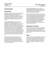
Product Bulletin Accessories Handwheels Handwheels for diaphragm actuators are often used as adjustable travel stops. They also provide a ready means of positioning the control valve in an emergency. The specifications in tables 5 and 6 apply to handwheels on both 657 and 667 Series actuators. For repeated or daily manual operation, the unit should be equipped with a side-mounted handwheel actuator. Top-Mounted Handwheels—Typical 657 and 667 actuators with handwheels mounted on the diaphragm case are shown in figure 2 (not available on a 667 actuator, size 80). On the 657 actuator, the handwheel...
Open the catalog to page 4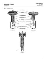
Product Bulletin Figure 1. Typical Actuators DIAPHRAGM CASINGS DIAPHRAGM DIAPHRAGM PLATE ACTUATOR SPRING ACTUATOR STEM SPRING SEAT SPRING ADJUSTOR STEM CONNECTOR YOKE TRAVEL INDICATOR DISK INDICATOR SCALE
Open the catalog to page 5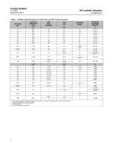
Product Bulletin61.1:657 September 2017 Table 1. Additional Specifications for Fisher 657 and 667 Series Actuators 1. These values are based on material limitations such as yoke, stem connection, diaphragm plate, and travel stop strengths. 2. Values also apply to 657-4 and 667-4 actuators. 5. H=Heavy actuator-to-valve bolting.
Open the catalog to page 6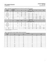
Product Bulletin61.1:657 September 2017 Table 2. Volumetric Casing Displacement for Fisher 657 and 667 Series Actuators
Open the catalog to page 7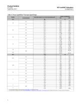
Product Bulletin61.1:657 September 2017 Table 4. Thrust Capabilities^) by Input Signal Range 1. For Size 76 667 actuators, contact your Emerson sales office or Local Business Partner. 2. Consult Fisher 657 and 667 instruction manuals (D100306X012, D100307X012, D100310X012, and D100311X012) for additional information on maximum pressure limitations.
Open the catalog to page 8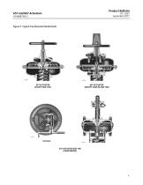
Product Bulletin Figure 2. Typical Top-Mounted Handwheels 657 ACTUATOR (EXCEPT SIZE 100) 667 ACTUATOR (EXCEPT SIZES 80 AND 100) 657 ACTUATOR SIZE 100 (GEAR DRIVEN)
Open the catalog to page 9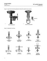
Product Bulletin Figure 3. Typical Side-Mounted Handwheels for Fisher 657 and 667 Series Actuators Figure 4. Adjustable Travel Stops STYLE 2 657 AND 657-4 DOWN STOP STYLE 10 667 DOWN STOP STYLE 11 667 UP AND DOWN STOP STYLE P2 667 UP AND DOWN STOP
Open the catalog to page 10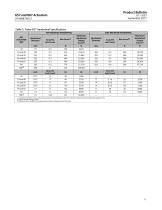
Product Bulletin61.1:657 September 2017 Table 5. Fisher 657 Handwheel Specifications 1. Tangential handwheel force required to produce the handwheel output force shown. (Proportional to handwheel output force). 2. Top-mounted with gear drive. 3. Maximum force available to compress the actuator spring and close the valve.
Open the catalog to page 11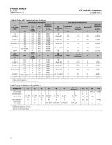
Product Bulletin61.1:657 September 2017 Table 6. Fisher 667 Handwheel Specifications
Open the catalog to page 12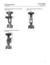
Product Bulletin Figure 5. Fisher 646 Electro-Pneumatic Transducer on 657 Actuator Figure 7. Fisher 4200 Position Transmitter on 667 Actuator Figure 6. Fisher 3582i Valve Positioner on 657 Actuator
Open the catalog to page 13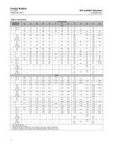
Product Bulletin61.1:657 September 2017 Table 8. Dimensions
Open the catalog to page 14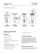
Product Bulletin 61.1:657 September 2017 Figure 8. Dimensions (also see table 8) Ordering Information When ordering, specify: 9. Ambient temperature range 1. On-off or throttling service 2. Input signal range 3. Maximum supply pressure 4. Valve body type and size with which the actuator will be used 5. Valve plug travel 6. Actuator thrust required with actuator stem both fully retracted and fully extended 7. Stroking time requirements, if critical 8. Seismic requirements, if critical Be sure to specify: actuator type number; whether a positioner is required; whether a top-mounted handwheel is...
Open the catalog to page 15All FISHER REGULATORS catalogs and technical brochures
 Fisher™ 8590 High-Performance
16 Pages
Archived catalogs
 167D Series Switching Valves
8 Pages
 CS400 Series
60 Pages
 cs200 series
40 Pages
 Type HSR Pressure Regulators
20 Pages
 R622 series
8 Pages
 S200 series
32 Pages
 310A Pressure Reducing Regulator
16 Pages
 ACE97 Pad-Depad Valve
16 Pages
 627F Pressure Reducing Regulator
12 Pages
 630 Regulator
16 Pages
 EZR Pressure Reducing Regulator
36 Pages
 Fisher® 377 Trip Valve
20 Pages
 Fisher® CAV4 Control Valve
28 Pages
 Fisher® HP Series Control Valves
28 Pages
 Fisher® HPNS Control Valve
36 Pages
 Fisher® YD and YS Control Valves
24 Pages
 Fisher® EZ easy-e Control Valve
40 Pages
 Fisher® D and DA Valves
12 Pages
 MR95 and MR98
2 Pages
 1301F, 1301G
12 Pages
 Regulators Mini Catalog
24 Pages
 CS 200 series
2 Pages
 LP-31
LP-3196 Pages
 FPSO Industry Solution
2 Pages
 Smartprocess™ Heater
5 Pages
 DeltaV Smart Switches
28 Pages
 Ovation Security Center
4 Pages
 The Criticality of Cooling
5 Pages
 CSI 6500 Overview
12 Pages
 DeltaV Controller Firewall
11 Pages
 Air Application Map
1 Page
 H200 Series Relief Valves
4 Pages
 1305 Series Regulators
4 Pages
 Large ET and ED Valves
20 Pages
 easy-e Cryogenic Valves
12 Pages
 Fisher™ YD and YS Control Valves
24 Pages
 Type 630 Regulator
16 Pages
 Fisher™ 585C Piston Actuators
16 Pages
 Type 630R Relief Valve
8 Pages
 Type 92B Pressure Reducing Valve
16 Pages
 Industrial Regulators
2 Pages
 LP-Gas Technologies
118 Pages
 R Series
2 Pages
 Run with higher performing,
16 Pages
 ™ Control Valves and Instruments
16 Pages
 Pressure Equivalents
1 Page
 Pipe and Tubing Sizing
1 Page


