- Catalogs
- FISHER REGULATORS
- ACE97 Pad-Depad Valve
ACE97 Pad-Depad Valve
1 /16Pages

ACE97 Pad-Depad Valve
1 /16Pages
Catalog excerpts

type aCe97 Pad-Depad valve • Bubble Tight Shutoff • Frictionless Pilot Valve • Pilot Controlled • Maximum Vapor Space Control • Stainless Steel Figure 1. Type ACE97 Pad-Depad Valve
Open the catalog to page 1
Bulletin 74.3:ACE97 Specifications Pad Specifications General Type ACE97 Specifications Pressure Registration External Maximum Operating Inlet Pressure(1) 200 psig / 13.8 bar Temperature Capabilities Nitrile (NBR): -20 to 180°F / -29 to 82°C Fluorocarbon (FKM): 0 to 212°F / -18 to 100°C Ethylenepropylene (EPDM - FDA): -20 to 212°F / -29 to 100°C Perfluoroelastomer (FFKM): -20 to 212°F / -29 to 100°C Maximum Main Valve Inlet Pressure(1) 200 psig 13.8 bar Control Pressure Ranges(1) See Table 1 Maximum and Minimum Differential Pressures(1) Minimum: 25 psig / 1.7 bar Maximum: 200 psig / 13.8 bar...
Open the catalog to page 2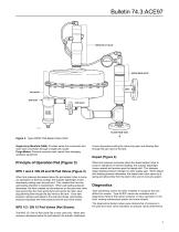
depad pilot valve Depad main valve vent actuator inlet filter Figure 2. Type ACE97 Pad-Depad Valve Parts Single Array Manifold (SAM): Provides sense line connection and main valve connection through a single tank nozzle. Purge Meters: Prevents corrosive tank vapors from damaging upstream equipment. Principle of Operation Pad (Figure 3) NPS 1 and 2 / DN 25 and 50 Pad Valves (Figure 3) When tank pressure decreases below the pad setpoint (due to pump out operations or thermal cooling), the actuator diaphragm moves downward pushing open the pad pilot. This creates flow from the pad loading chamber...
Open the catalog to page 3
Bulletin 74.3:ACE97 loading pressure exhausted back to tank on/off diagnostic gauge depad pilot adjustable deadband poppet cage controlled pressure range spring depad main valve o-ring seat inlet inlet bleed rolling diaphragm sensing connection open pilot diagnostic port main valve spring INLET PRESSURE ATMOSPHERIC PRESSURE TANK PRESSURE PILOT LOADING PRESSURE VENT HEADER PRESSURE tank connection INLET BLEED PRESSURE Figure 3. Type ACE97 Pad On / Depad Off loading pressure exhausted back to tank depad pilot controlled pressure range spring depad main valve o-ring seat on/off diagnostic gauge...
Open the catalog to page 4
Bulletin 74.3:ACE97 Table 1. Control Pressure Ranges Controlled Pressure RANGEs Pad Setpoint Depad Setpoint (Above Pad) SPRING FREE LENGTH SPRING WIRE DIAMETER 1. Two nested springs are used. System Sizing Tank Blanketing systems must be properly sized to have capacity to supply enough blanketing gas to maintain the setpoint pressure, yet large enough to vent excess gas without having tank vapor space pressure rise above allowable limits. Pad valves must not be so large that they cause overpressure. Sizing must also take into account applicable codes and standards as they apply to the installation....
Open the catalog to page 5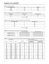
Bulletin 74.3:ACE97 Table 2. Flow Rate Conversion multiply maximum pump rate U.S. GPM U.S. GPH m3/hr Barrels/hr Barrels/day to obtaiN: SCFH SCFH Nm3/h SCFH SCFH Table 3. Correction Factors (For Converting Nitrogen Flow Rates to Other Gas Flow Rates) SPECIFIC GRAVITY 0.60 1.00 1.52 Correction Factor = Table 4. Correction Factors (For Converting Air Flow Rates to Other Gas Flow Rates) Table 5. Flow Rate Requirements for Liquid Pump-In Pump-Out per API 2000 Pump-Out (Inbreathing) Pump-In (Outbreathing) Flashpoint > 100°F / 38°C or Normal Boiling Point > 300°F / 149°C 5.6 SCFH / 0.15 Nm3/h of air...
Open the catalog to page 6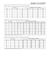
Table 8. NPS 1 / DN 25 Pad Valve Capacities of 0.97 Specific Gravity Nitrogen INLET PRESSURE
Open the catalog to page 7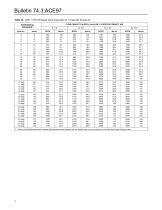
Bulletin 74.3:ACE97 Table 10. NPS 1 / DN 25 Depad Valve Capacities of 1.0 Specific Gravity Air flow capacity in scfh / Nm3/h of 1.0 specific gravity air 1.0 psig 1.1 psig 1.2 psig 1.3 psig 1.4 psig 1.5 psig 1.6 psig 1.7 psig 1.8 psig 1.9 psig 2.0 psig 2.1 psig 2.2 psig 2.3 psig 2.4 psig 2.5 psig 2.6 psig 2.7 psig 2.8 psig 1. Always use the differential pressure between tank pressure (depad setpoint) and vent header (vapor recovery) pressure to calculate flow through the depad valve.
Open the catalog to page 8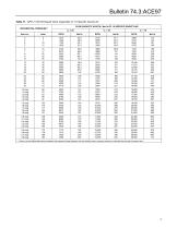
Bulletin 74.3:ACE97 Table 11. NPS 2 / DN 50 Depad Valve Capacities of 1.0 Specific Gravity Air flow capacity in scfh / Nm3/h of 1.0 specific gravity air 1.0 psig 1.1 psig 1.2 psig 1.3 psig 1.4 psig 1.5 psig 1.6 psig 1.7 psig 1.8 psig 1.9 psig 2.0 psig 2.1 psig 2.2 psig 2.3 psig 2.4 psig 2.5 psig 2.6 psig 2.7 psig 2.8 psig 1. Always use the differential pressure between tank pressure (depad setpoint) and vent header (vapor recovery) pressure to calculate flow through the depad valve.
Open the catalog to page 9
Bulletin 74.3:ACE97 Table 12. NPS 3 / DN 80 Depad Valve Capacities of 1.0 Specific Gravity Air flow capacity in scfh / Nm3/h of 1.0 specific gravity air 1.0 psig 1.1 psig 1.2 psig 1.3 psig 1.4 psig 1.5 psig 1.6 psig 1.7 psig 1.8 psig 1.9 psig 2.0 psig 2.1 psig 2.2 psig 2.3 psig 2.4 psig 2.5 psig 2.6 psig 2.7 psig 2.8 psig 1. Always use the differential pressure between tank pressure (depad setpoint) and vent header (vapor recovery) pressure to calculate flow through the depad valve.
Open the catalog to page 10
Bulletin 74.3:ACE97 Table 13. NPS 4 / DN 100 Depad Valve Capacities of 1.0 Specific Gravity Air flow capacity in scfh / Nm3/h of 1.0 specific gravity air 1.0 psig 1.1 psig 1.2 psig 1.3 psig 1.4 psig 1.5 psig 1.6 psig 1.7 psig 1.8 psig 1.9 psig 2.0 psig 2.1 psig 2.2 psig 2.3 psig 2.4 psig 2.5 psig 2.6 psig 2.7 psig 2.8 psig 1. Always use the differential pressure between tank pressure (depad setpoint) and vent header (vapor recovery) pressure to calculate flow through the depad valve.
Open the catalog to page 11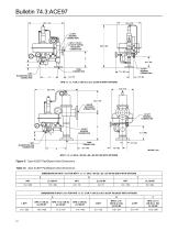
1/2 NPT SENSING CONNECTION NPS 1 / DN 25, CL150 RF VAPOR RECOVERY CONNECTION 12.3 / 312 VAPOR RECOVERY CONNECTION 1/2 NPT SENSING CONNECTION TANK CONNECTION Figure 5. Type ACE97 Pad/Depad Valve Dimensions Table 14. Type ACE97 Pad/Depad Valve Dimensions DIMENSIONS IN INCH / mm FOR NPS 1 x 1 x 1 OR 2 / DN 25 x 25 x 25 OR 50 BODy WITH OPTIONS A DIMENSIONS IN INCH / mm FOR NPS 1 x 3 x 3 or 4 / DN 25 x 80 x 80 OR 100 BODy WITH OPTIONS A
Open the catalog to page 12
VAPOR RECOVERY CONNECTION 1/2 NPT SENSING CONNECTION C NPS 1 or 2 / DN 25 or 50, CL150 RF VAPOR RECOVERY CONNECTION TANK CONNECTION NPS 1/2 x 1 x 2 / DN 15 x 25 x 50 WITH SINGLE ARRAY MANIFOLD Figure 5. Type ACE97 Pad/Depad Valve Dimensions (continued) Table 14. Type ACE97 Pad/Depad Valve Dimensions (continued) DIMENSIONS IN INCH / mm FOR NPS 1/2 x 1 x 1 OR 2 / DN 15 x 25 x 25 OR 50 BODy WITH OPTIONS A DIMENSIONS IN INCH / mm FOR NPS 1/2 x 1 x 2 / DN 15 x 25 x 50 BODY WITH SINGLE ARRAY MANIFOLD A
Open the catalog to page 13All FISHER REGULATORS catalogs and technical brochures
 ™ Control Valves and Instruments
16 Pages
 Run with higher performing,
16 Pages
 R Series
2 Pages
 LP-Gas Technologies
118 Pages
 Industrial Regulators
2 Pages
 Type 92B Pressure Reducing Valve
16 Pages
 Type 630R Relief Valve
8 Pages
 Fisher™ 585C Piston Actuators
16 Pages
 Type 630 Regulator
16 Pages
 Fisher™ YD and YS Control Valves
24 Pages
 easy-e Cryogenic Valves
12 Pages
 Large ET and ED Valves
20 Pages
 1305 Series Regulators
4 Pages
 H200 Series Relief Valves
4 Pages
 Air Application Map
1 Page
 DeltaV Controller Firewall
11 Pages
 CSI 6500 Overview
12 Pages
 The Criticality of Cooling
5 Pages
 Ovation Security Center
4 Pages
 DeltaV Smart Switches
28 Pages
 Smartprocess™ Heater
5 Pages
 FPSO Industry Solution
2 Pages
 LP-31
LP-3196 Pages
 CS 200 series
2 Pages
 Regulators Mini Catalog
24 Pages
 1301F, 1301G
12 Pages
 MR95 and MR98
2 Pages
 Fisher® D and DA Valves
12 Pages
 Fisher® EZ easy-e Control Valve
40 Pages
 Fisher® YD and YS Control Valves
24 Pages
 Fisher® HPNS Control Valve
36 Pages
 Fisher® HP Series Control Valves
28 Pages
 Fisher® CAV4 Control Valve
28 Pages
 Fisher® 377 Trip Valve
20 Pages
 EZR Pressure Reducing Regulator
36 Pages
 630 Regulator
16 Pages
 627F Pressure Reducing Regulator
12 Pages
 310A Pressure Reducing Regulator
16 Pages
 S200 series
32 Pages
 R622 series
8 Pages
 Type HSR Pressure Regulators
20 Pages
 cs200 series
40 Pages
 CS400 Series
60 Pages
 167D Series Switching Valves
8 Pages


Archived catalogs
 Pressure Equivalents
1 Page
 Pipe and Tubing Sizing
1 Page


- SARRALLE manual valve
- SARRALLE control valve
- SARRALLE stainless steel valve
- SARRALLE ball valve
- SARRALLE pneumatic valve
- Threaded valve
- SARRALLE regulating valve
- Flange valve
- SARRALLE shut-off valve
- SARRALLE electric valve
- ISO valve
- Level limit switch
- Pressure gauge
- SARRALLE pressure regulator
- SARRALLE gas valve
- Valve with handwheel
- Liquid level detector
- SARRALLE pneumatically-operated valve
- SARRALLE level sensor