
- Catalogs
- FISHER REGULATORS
- 912N Series Pressure Regulators

912N Series Pressure Regulators

912N Series Pressure Regulators
The 912N Series pressure regulators are direct-operated, spring-loaded devices used in various industrial applications. They feature a limited-capacity internal relief across the diaphragm to minimize overpressure. The outlet pressure ranges vary according to construction.
Features
- Accurate and Sensitive Control: The disk/lever assembly is attached to a roller-style pivot for smoother action, with handwheel construction available for pressure setting adjustments.
- Versatility: Suitable for various gaseous fluids, including natural gas, propane, and air.
- Weather and Insect Protection: A "drip lip" vent helps resist blockage during icing conditions.
- Easy Maintenance: Diaphragm and disk/lever assembly can be replaced without removing the regulator from the pipeline.
Principle of Operation
When downstream demand decreases, pressure under the diaphragm increases, reducing gas flow. If demand increases, the pressure decreases, allowing more gas flow. The regulators include an internal relief valve for overpressure protection.
Specifications
- Body Sizes and End Connection Styles: Inlet: 1/4 NPT, Outlet: 1/4 or 3/8 NPT
- Maximum Allowable Inlet Pressure: 250 psig (17.2 bar)
- Outlet Pressure Ranges: See Table 1
- Temperature Capabilities: -20° to 160°F (-29° to 71°C)
- Construction Materials: Zinc body/lower casing, plated carbon steel spring case bolting, fluorocarbon disk, nitrile diaphragm, etc.
Overpressure Protection
The 912N Series regulators have lower outlet pressure ratings than inlet pressure ratings. Complete downstream protection is needed if the actual inlet pressure exceeds the outlet pressure rating.
Installation
Regulators can be installed in any position, but the spring case vent should point down for outside installations. If gas escaping through the internal relief valve could be hazardous, the vent should be piped to a safe location.
Capacity Information
Natural gas regulating capacities at selected inlet pressures and outlet pressure settings are provided in Tables 2 and 3. Conversion factors are available for other gases.
Ordering Information
When ordering, specify the application, gas composition, temperature range, inlet pressures, desired outlet pressure, flow rates, and piping sizes. Review the specifications and select the desired options.
Catalog excerpts

Bulletin 71.1:912N April 2010 912N Series Pressure Regulators Introduction The 912N Series direct-operated, spring-loaded regulators are used in a variety of service and industrial applications. These regulators have limited-capacity internal relief across the diaphragm (see Figure 2) to help minimize overpressure. Any outlet pressure above the start-to-discharge point of the non-adjustable relief valve spring moves the diaphragm off the relief valve seat, allowing excess pressure to bleed out through the screened spring case vent. Inlet pressure capabilities are the same for all regulators described in this bulletin. However, outlet pressure ranges vary according to construction (see Table 1). Features • Accurate and Sensitive Control—Disk/lever assembly is attached to a roller-style pivot for smoother action. Handwheel construction is available for adjustment of the pressure setting. • Versatility—These regulators are suitable for a variety of gaseous fluids, including natural gas, propane, and air. They are often used to supply loading pressure to other units. P1024 Figure 1. 912N Series Regulator regulator spring • Weather and Insect Protection—“Drip lip” vent helps resist blockage during icing conditions. When the regulator is installed with the vent pointing down, any ice that builds up forms a protective sheath that helps keep the opening unobstructed. The vent screen helps prevent foreign material from entering the spring case and clogging or otherwise hindering regulator operation. Relief Valve Spring pusher post assembly Relief Valve Seat vent screen diaphragm • Easy Maintenance—Diaphragm and disk/lever assembly can be replaced without removing the regulator from the pipeline. Principle of Operation M1021 Valve disk disk/lever assembly D100124X012 Body/Lower Refer to Figure 2. When downstream demand decreases, INLET PRESSURE Casing OUTLET PRESSURE ATMOSPHERIC PRESSURE the pressure under the diaphragm increases. This pressure Inlet PRESSURE INLETpressure overcomes the regulator setting (which is set by a spring). OUTLET PRESSURE OUTLETpressure Through the action of the pusher post assembly, the valve ATMOSPHERIC pressure ATMOSPHERIC PRESSURE disk moves closer to the orifice and reduces gas flow. If demand downstream increases, pressure under the diaphragm Figure 2. 912N Series Operational Schematic decreases. Spring force pushes the pusher post assembly (Standard Spring Case Vent Shown) www.fisherregulators.com
Open the catalog to page 1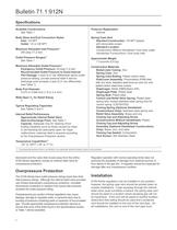
Bulletin 71.1:912N Specifications Available Constructions See Table 1 Pressure Registration Internal Body Sizes and End Connection Styles Inlet: 1/4 NPT Outlet: 1/4 or 3/8 NPT Maximum Allowable Inlet Pressure(1) 250 psig (17,2 bar) Spring Case Vent Standard Construction: 1/8 NPT tapped with removable screen Standard Location Constructions Without Handwheel: Over body outlet Handwheel Constructions: Over body inlet Outlet Pressure Ranges(1) See Table 1 Approximate Weight 1.3 pounds (0,6 kg) Maximum Allowable Outlet Pressure(1) Emergency Outlet Pressure: 20 psig (1,4 bar) Recommended Outlet Pressure...
Open the catalog to page 2
Table 1. Outlet Pressure Range Data Table 2. Capacities for Type 912N Regulators without Handwheel (Body Size 1/4 x 3/8 NPT) Table 3. Capacities for Type 912N Regulators with Handwheel (Body Size 1/4 x 3/8 NPT)
Open the catalog to page 3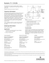
Bulletin 71.1:912N be protected from corrosive chemicals, debris, weather, condensation, or anything else that might clog or enter the spring case. 3.2 (81) 0.2 (5) Regulator dimensions are shown in Figure 3. Capacity Information 2.8 (71) Natural gas regulating capacities at selected inlet pressures and outlet pressure settings are given in Tables 2 and 3. Flows are in SCFH (60°F and 14.7 psia) of 0.6 specific gravity natural gas. To determine the equivalent capacities for other gases, multiply the table capacity by the following appropriate conversion factor: 0.775 for air, 0.789 for nitrogen,...
Open the catalog to page 4All FISHER REGULATORS catalogs and technical brochures
 Fisher™ 8590 High-Performance
16 Pages
 bulletin-fisher-657-and-667
16 Pages
Archived catalogs
 167D Series Switching Valves
8 Pages
 CS400 Series
60 Pages
 cs200 series
40 Pages
 Type HSR Pressure Regulators
20 Pages
 R622 series
8 Pages
 S200 series
32 Pages
 310A Pressure Reducing Regulator
16 Pages
 ACE97 Pad-Depad Valve
16 Pages
 627F Pressure Reducing Regulator
12 Pages
 630 Regulator
16 Pages
 EZR Pressure Reducing Regulator
36 Pages
 Fisher® 377 Trip Valve
20 Pages
 Fisher® CAV4 Control Valve
28 Pages
 Fisher® HP Series Control Valves
28 Pages
 Fisher® HPNS Control Valve
36 Pages
 Fisher® YD and YS Control Valves
24 Pages
 Fisher® EZ easy-e Control Valve
40 Pages
 Fisher® D and DA Valves
12 Pages
 MR95 and MR98
2 Pages
 1301F, 1301G
12 Pages
 Regulators Mini Catalog
24 Pages
 CS 200 series
2 Pages
 LP-31
LP-3196 Pages
 FPSO Industry Solution
2 Pages
 Smartprocess™ Heater
5 Pages
 DeltaV Smart Switches
28 Pages
 Ovation Security Center
4 Pages
 The Criticality of Cooling
5 Pages
 CSI 6500 Overview
12 Pages
 DeltaV Controller Firewall
11 Pages
 Air Application Map
1 Page
 H200 Series Relief Valves
4 Pages
 1305 Series Regulators
4 Pages
 Large ET and ED Valves
20 Pages
 easy-e Cryogenic Valves
12 Pages
 Fisher™ YD and YS Control Valves
24 Pages
 Type 630 Regulator
16 Pages
 Fisher™ 585C Piston Actuators
16 Pages
 Type 630R Relief Valve
8 Pages
 Type 92B Pressure Reducing Valve
16 Pages
 Industrial Regulators
2 Pages
 LP-Gas Technologies
118 Pages
 R Series
2 Pages
 Run with higher performing,
16 Pages
 ™ Control Valves and Instruments
16 Pages
 Pressure Equivalents
1 Page
 Pipe and Tubing Sizing
1 Page


- Manual valve
- FISHER control valve
- FISHER stainless steel valve
- Ball valve
- FISHER pneumatic valve
- Threaded valve
- Regulating valve
- Flange valve
- On/off valve
- Electric valve
- ISO valve
- Pressure gauge
- Level limit switch
- Gas valve
- Valve with handwheel
- FISHER pneumatically-operated valve
- Liquid level detector
- Butterfly valve