
- Catalogs
- FISHER REGULATORS
- 630 Regulator

630 Regulator

630 Regulator
The Type 630 Big Joe™ regulators are direct-operated, spring-loaded pressure reducing regulators available in 1 and 2-inch sizes. They are designed to handle maximum inlet pressures up to 1500 psig and outlet pressures ranging from 3 to 500 psig. These regulators are suitable for natural gas, air, and other gases, and can be converted to a relief valve or used as a high-pressure industrial regulator.
- High-Pressure Capabilities: Supports inlet pressures up to 1500 psig and control pressures up to 500 psig.
- Rugged Construction: The compact and sturdy design ensures reliability and longevity.
- Better Low-Pressure Control: Features a larger diaphragm area for accurate low-pressure settings.
- Sour Gas Service Capability: Optional materials are available for sour gases, compliant with NACE MR0175 standards.
- Body Sizes: Available in 1 and 2-inch sizes.
- End Connection Style: Options include NPT, ASME CL150 RF, CL300 RF, or CL600 RF.
- Maximum Inlet Pressure: Up to 1500 psig.
- Maximum Outlet Pressure: Up to 500 psig.
- Temperature Capabilities: Ranges from -20 to 180°F for Nitrile, Nylon, Neoprene; 0 to 300°F for Fluorocarbon, PTFE.
- Construction Materials: Options include a cast iron or steel body, with brass or stainless steel orifice.
The regulators can be installed in any position, ensuring that vent openings are protected against foreign material. The flow direction must follow the arrow indicated on the regulator body.
Overpressure protection is required if the inlet pressure exceeds the outlet pressure rating. Regulators should be inspected for damage following overpressure conditions.
The outlet pressure is registered beneath the diaphragm, and the valve opens or closes based on the outlet pressure relative to the set pressure.
Flow capacities are provided in SCFH and Nm3/h for natural gas, with conversion factors available for other gases.
Catalog excerpts

Type 630 Regulator Introduction The Type 630 Big Joe™ regulators are directoperated, spring-loaded, pressure reducing regulators. They are available in 1 and 2-inch / DN 25 and 50 body sizes, and they are designed for maximum inlet pressures to 1500 psig / 103 bar and outlet pressures from 3 to 500 psig / 0.21 to 34.5 bar. The Type 630 can be used with natural gas, air, or a variety of other gases for such applications as first-stage farm-tap regulators or high-pressure industrial regulators. The Type 630 can be converted in the field to a relief valve or is available as the Type 630R relief valve/backpressure regulator; refer to the separate Type 630R Bulletin (71.4:630R) for information. Features • High-Pressure Capabilities—Inlet pressures up to 1500 psig / 103 bar and control pressures up to 500 psig / 34.5 bar. • Rugged Construction—Compact, sturdy design and solid metal construction provide a strong, reliable, long-lasting regulator. • Better Low-Pressure Control—The Type 630 is available in both high-pressure and low-pressure constructions; the low-pressure units have a larger diaphragm area to provide more accurate control of low-pressure settings. Figure 1. Type 630 Big Joe High-Pressure Regulator The manufacturing processes and materials used by Fisher® Controls assure that all products specified for sour gas service comply with the chemical and physical requirements of NACE International MR0175. • Sour Gas Service Capability—Optional materials are available for applications handling sour gases. These constructions comply with the recommendations of the NACE International MR0175.
Open the catalog to page 1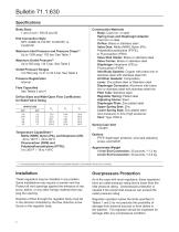
Bulletin 71.1:630 Specifications Body Sizes 1 and 2-inch / DN 25 and 50 End Connection Style NPT, ASME CL150 RF, CL300 RF, or CL600 RF Maximum Inlet Pressure and Pressure Drops(1) Up to 1500 psig / 103 bar, See Table 1 Maximum Outlet Pressure(1) Up to 500 psig / 34.5 bar, See Table 2 Outlet Pressure Ranges 3 to 500 psig / 0.21 to 34.5 bar, See Table 2 Pressure Registration Internal Flow Capacities See Tables 3 and 4 Orifice Sizes and Wide-Open Flow Coefficients for Relief Valve Sizing ORIFICE SIZE Inch Temperature Capabilities(1) Nitrile (NBR), Nylon (PA), and Neoprene (CR): -20 to 180°F / -29...
Open the catalog to page 2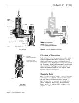
SPRING CASE DIAPHRAGM CONNECTOR DIAPHRAGM ADAPTOR VALVE DISK AND HOLDER INLET PRESSURE OUTLET PRESSURE ATMOSPHERIC PRESSURE INLET ADAPTOR Figure 3. Type 630 Operational Schematic FULL SECTION PITOT TUBE [1-INCH / DN 25 SIZE ONLY] REGISTRATION HOLE [2-INCH / DN 50 SIZE ONLY] Principle of Operations Refer to Figure 2. In the regulator construction, outlet pressure registers beneath the diaphragm. As long as the outlet pressure is less than the set pressure, spring force on the diaphragm causes the lever to hold the valve open. When the outlet pressure exceeds the set pressure, the diaphragm moves...
Open the catalog to page 3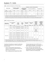
Bulletin 71.1:630 Table 1. Maximum Inlet Pressure and Pressure Drops MAXIMUM ALLOWABLE PRESSURE DROPS MAXIMUM ALLOWABLE INLET PRESSURE(1) ORIFICE SIZES Nylon (PA) and Polytetrafluoroethylene (PTFE) Disk psig Nitrile (NBR) Disk psig 1. Inlet pressure must not exceed the sum of the actual outlet pressure setting and the maximum allowable pressure drop. For example, with an outlet pressure setting of 200 psig / 13.8 bar and a 3/8-inch / 9.5 mm orifice with a maximum allowable pressure drop of 500 psid / 34.5 bar d, the maximum inlet pressure is 700 psig / 48.3 bar. 2. Nitrile (NBR) valve disks are...
Open the catalog to page 4
Bulletin 71.1:630 Table 3. 1-Inch / DN 25 Body Capacities (Based on 20% Droop) OUTLET PRESSURE RANGE, SPRING PART NUMBER, AND COLOR INLET PRESSURE 1-INCH / DN 25 BODY CAPACITIES IN SCFH / Nm3/h OF 0.6 SPECIFIC GRAVITY OF NATURAL GAS OUTLET PRESSURE Orifice Size, Inches / mm 1/8 / 3.2 Olive Drab
Open the catalog to page 5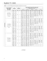
Bulletin 71.1:630 Table 3. 1-Inch / DN 25 Body Capacities (Based on 20% Droop) (continued) OUTLET PRESSURE RANGE, SPRING PART NUMBER, AND COLOR INLET PRESSURE 1-INCH / DN 25 BODY CAPACITIES IN SCFH / Nm3/h OF 0.6 SPECIFIC GRAVITY OF NATURAL GAS OUTLET PRESSURE Orifice Size, Inches / mm 1/8 / 3.2 Olive Drab
Open the catalog to page 6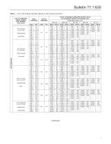
Bulletin 71.1:630 Table 3. 1-Inch / DN 25 Body Capacities (Based on 20% Droop) (continued) OUTLET PRESSURE RANGE, SPRING PART NUMBER, AND COLOR HIGH PRESSURE Olive Drab 150 to 200 psig / 10.3 to 13.8 bar 0Y066427022 Green Stripe INLET PRESSURE 1-INCH / DN 25 BODY CAPACITIES IN SCFH / Nm3/h OF 0.6 SPECIFIC GRAVITY OF NATURAL GAS OUTLET PRESSURE Orifice Size, Inches / mm 1/8 / 3.2
Open the catalog to page 7
Bulletin 71.1:630 Table 3. 1-Inch / DN 25 Body Capacities (Based on 20% Droop) (continued) OUTLET PRESSURE RANGE, SPRING PART NUMBER, AND COLOR INLET PRESSURE 1-INCH / DN 25 BODY CAPACITIES IN SCFH / Nm3/h OF 0.6 SPECIFIC GRAVITY OF NATURAL GAS OUTLET PRESSURE Orifice Size, Inches / mm 1/8 / 3.2 HIGH PRESSURE 275 to 500 psig / 19.0 to 34.5 bar 1K370927082 Yellow Stripe Blue Stripe Green Stripe
Open the catalog to page 8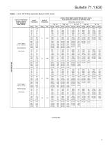
Bulletin 71.1:630 Table 4. 2-Inch / DN 50 Body Capacities (Based on 20% Droop) OUTLET PRESSURE RANGE, SPRING PART NUMBER, AND COLOR INLET PRESSURE 2-INCH / DN 50 BODY CAPACITIES IN SCFH / Nm3/h OF 0.6 SPECIFIC GRAVITY OF NATURAL GAS OUTLET PRESSURE Orifice Size, Inches / mm 1/8 / 3.2 Olive Drab
Open the catalog to page 9
Bulletin 71.1:630 Table 4. 2-Inch / DN 50 Body Capacities (Based on 20% Droop) (continued) OUTLET PRESSURE RANGE, SPRING PART NUMBER, AND COLOR INLET PRESSURE 2-INCH / DN 50 BODY CAPACITIES IN SCFH / Nm3/h OF 0.6 SPECIFIC GRAVITY OF NATURAL GAS OUTLET PRESSURE Orifice Size, Inches / mm 1/8 / 3.2 Olive Drab
Open the catalog to page 10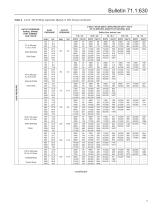
Bulletin 71.1:630 Table 4. 2-Inch / DN 50 Body Capacities (Based on 20% Droop) (continued) OUTLET PRESSURE RANGE, SPRING PART NUMBER, AND COLOR HIGH PRESSURE 150 to 200 psig / 10.3 to 13.8 bar 0Y066427022 Green Stripe INLET PRESSURE 2-INCH / DN 50 BODY CAPACITIES IN SCFH / Nm3/h OF 0.6 SPECIFIC GRAVITY OF NATURAL GAS OUTLET PRESSURE Orifice Size, Inches / mm 1/8 / 3.2
Open the catalog to page 11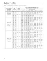
Bulletin 71.1:630 Table 4. 2-Inch / DN 50 Body Capacities (Based on 20% Droop) (continued) OUTLET PRESSURE RANGE, SPRING PART NUMBER, AND COLOR INLET PRESSURE 2-INCH / DN 50 BODY CAPACITIES IN SCFH / Nm3/h OF 0.6 SPECIFIC GRAVITY OF NATURAL GAS OUTLET PRESSURE Orifice Size, Inches / mm 1/8 / 3.2 HIGH PRESSURE 275 to 500 psig / 19.0 to 34.5 bar 1K370927082 Yellow Stripe Blue Stripe Green Stripe
Open the catalog to page 12All FISHER REGULATORS catalogs and technical brochures
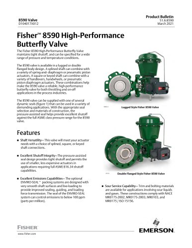 Fisher™ 8590 High-Performance
16 Pages
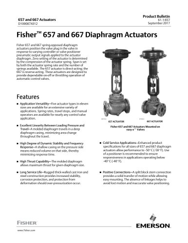 bulletin-fisher-657-and-667
16 Pages
Archived catalogs
 167D Series Switching Valves
8 Pages
 CS400 Series
60 Pages
 cs200 series
40 Pages
 Type HSR Pressure Regulators
20 Pages
 R622 series
8 Pages
 S200 series
32 Pages
 310A Pressure Reducing Regulator
16 Pages
 ACE97 Pad-Depad Valve
16 Pages
 627F Pressure Reducing Regulator
12 Pages
 EZR Pressure Reducing Regulator
36 Pages
 Fisher® 377 Trip Valve
20 Pages
 Fisher® CAV4 Control Valve
28 Pages
 Fisher® HP Series Control Valves
28 Pages
 Fisher® HPNS Control Valve
36 Pages
 Fisher® YD and YS Control Valves
24 Pages
 Fisher® EZ easy-e Control Valve
40 Pages
 Fisher® D and DA Valves
12 Pages
 MR95 and MR98
2 Pages
 1301F, 1301G
12 Pages
 Regulators Mini Catalog
24 Pages
 CS 200 series
2 Pages
 LP-31
LP-3196 Pages
 FPSO Industry Solution
2 Pages
 Smartprocess™ Heater
5 Pages
 DeltaV Smart Switches
28 Pages
 Ovation Security Center
4 Pages
 The Criticality of Cooling
5 Pages
 CSI 6500 Overview
12 Pages
 DeltaV Controller Firewall
11 Pages
 Air Application Map
1 Page
 H200 Series Relief Valves
4 Pages
 1305 Series Regulators
4 Pages
 Large ET and ED Valves
20 Pages
 easy-e Cryogenic Valves
12 Pages
 Fisher™ YD and YS Control Valves
24 Pages
 Type 630 Regulator
16 Pages
 Fisher™ 585C Piston Actuators
16 Pages
 Type 630R Relief Valve
8 Pages
 Type 92B Pressure Reducing Valve
16 Pages
 Industrial Regulators
2 Pages
 LP-Gas Technologies
118 Pages
 R Series
2 Pages
 Run with higher performing,
16 Pages
 ™ Control Valves and Instruments
16 Pages
 Pressure Equivalents
1 Page
 Pipe and Tubing Sizing
1 Page


- Manual valve
- FISHER control valve
- FISHER stainless steel valve
- Ball valve
- FISHER pneumatic valve
- Threaded valve
- Regulating valve
- Flange valve
- On/off valve
- Electric valve
- ISO valve
- Pressure gauge
- Level limit switch
- Gas valve
- Valve with handwheel
- FISHER pneumatically-operated valve
- Liquid level detector
- Butterfly valve