Catalog excerpts

Type 627F Pilot-Operated Pressure Reducing Regulator Figure 1. Type 627F Pressure Reducing Regulators The Type 627F pilot-operated (Type 6351F pilot) pressure reducing regulator (Figure 1) provides superior performance when used in pressure-factor measurement (fixed-factor billing) applications. The Type 627F includes a factory-installed Type 6351F pilot and has external registration that requires a downstream control line. Features • Accurate for Pressure-Factor Measurement Applications—Pilot action controls pressure to within ±1 percent of the absolute outlet pressure (psia) setting at full valve disk travel, resulting in higher capacity than could be obtained without a pilot. This capability results in low-pressure variations over broad flow ranges and inlet pressure ranges. pipeline. A two-bolt connection between the body and diaphragm casing simplifies disassembly for maintenance. • Installation Adaptability—The diaphragm case and/or regulator body can be rotated in any of four positions to allow regulator installation in locations with limited space. The regulator may be installed in any position without affecting operation as long as the spring case vent is protected from the elements. • Tamper-Resistant—An adjusting screw locknut and protective cap (Figure 2) is standard on all Type 6351F pilots to discourage tampering with the pressure setting. • Wide Range of Flow Capabilities—A selection of body and orifice sizes is available to satisfy various flow requirements. • Tight Shutoff Capability—A flat-faced disk of Nitrile (NBR) provides excellent shutoff capability. • Easy to Maintain—Trim parts can be replaced without removing the regulator body from the
Open the catalog to page 1
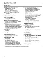
Body Sizes and End Connection Styles Construction Materials (continued) Ductile iron: 3/4, 1, or 2 NPT Disk Assembly: Aluminum (standard) or Steel: 3/4, 1, or 2 NPT; Stainless steel holder with Nitrile (NBR) disk NPS 1 or 2 / DN 25 or 50, CL150 RF, O-Rings and Diaphragm: Nitrile (NBR) CL300 RF, CL600 RF, PN 16/25/40 RF Tension Spring: Plated steel Type 6351F Pilot Maximum Inlet and Differential Pressures(1) Body: Stainless steel See Table 2 Spring Case: Aluminum Diaphragm: Nylon fabric coated with Nitrile (NBR) Minimum Pressure Differential Inner Valve Plug: Stainless steel/Nitrile (NBR) or...
Open the catalog to page 2
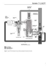
Bulletin 71.2:627F FIELD INSTALLED DOWNSTREAM CONTROL LINE SPRING SEAT BOLT, THIS IS NOT AN ADJUSTING SCREW FILTER (FACTORY INSTALLATION OPTIONAL) RESTRICTION (BLEED) TENSION SPRING PILOT DIAPHRAGM MAIN REGULATOR DIAPHRAGM VALVE DISK PILOT ADJUSTING SCREW PILOT SUPPLY TUBING (FACTORY INSTALLATION OPTIONAL) A6558 INLET PRESSURE OUTLET PRESSURE ATMOSPHERIC PRESSURE LOADING PRESSURE Figure 2. Type 627F Pilot-Operated Pressure Reducing Regulator Operational Schematic
Open the catalog to page 3
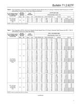
Bulletin 71.2:627F Table 1. Outlet Pressure Ranges PILOT CONTROL SPRING INFORMATION OUTLET PRESSURE RANGE PILOT TYPE Wire Diameter Color Code Unpainted Red Free Length Table 2. Maximum Allowable Inlet Pressures and Pressure Differential ORIFICE SIZE MAXIMUM INLET PRESSURE MAXIMUM PRESSURE DIFFERENTIAL Table 3. Additional Specifications ALLOWABLE INLET PRESSURE RANGE FOR MAINTAINING OUTLET PRESSURE WITHIN ±1% OF THE ABSOLUTE OUTLET PRESSURE SETTING(1) ORIFICE SIZE 1. For best performance, outlet pressure setting should be made using an inlet pressure that is midway between the highest and...
Open the catalog to page 4
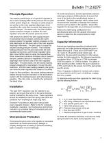
Bulletin 71.2:627F Principle Operation The superior performance of a Type 627F regulator is due to the amplifying effect of the pilot and the two-path control system (Figure 2). Changes in outlet pressure act quickly on the main regulator diaphragm which repositions the valve disk to provide fast response to system changes. Simultaneously, the pilot amplifies system pressure changes to position the main regulator valve disk for precise pressure control. Inlet pressure is used for the pilot supply pressure. If downstream flow increases, lowering the outlet pressure below the regulator...
Open the catalog to page 5
Bulletin 71.2:627F Table 6. Flow Capacities in SCFH / Nm3/h of 0.6 Specific Gravity Natural Gas at 1% Droop in Absolute Outlet Pressure for 3/4 NPT (Downstream Control Line in Body Size Piping) PILOT SPRING RANGE, PART NUMBER, AND COLOR CODE OUTLET PRESSURE SETTING psig Orifice Diameter, Inches / mm – Maximum operating inlet pressure is exceeded.
Open the catalog to page 6
Bulletin 71.2:627F Table 6. Flow Capacities in SCFH / Nm3/h of 0.6 Specific Gravity Natural Gas at 1% Droop in Absolute Outlet Pressure for 3/4 NPT (Downstream Control Line in Body Size Piping) (continued) PILOT SPRING RANGE, PART NUMBER, AND COLOR CODE 35 to 100 psig / 2.4 to 6.9 bar 1K748527202 Red OUTLET PRESSURE SETTING psig 100 INLET PRESSURE – Maximum operating inlet pressure is exceeded. Table 7. Flow Capacities in SCFH / Nm3/h of 0.6 Specific Gravity Natural Gas at 1% Droop in Absolute Outlet Pressure for NPS 1 / DN 25 (Downstream Control Line in Body Size Piping) PILOT SPRING...
Open the catalog to page 7
Bulletin 71.2:627F Table 7. Flow Capacities in SCFH / Nm3/h of 0.6 Specific Gravity Natural Gas at 1% Droop in Absolute Outlet Pressure for NPS 1 / DN 25 (Downstream Control Line in Body Size Piping) (continued) PILOT SPRING RANGE, PART NUMBER, AND COLOR CODE OUTLET PRESSURE SETTING psig INLET PRESSURE Orifice Diameter, Inches / mm – Maximum operating inlet pressure is exceeded. Table 8. low Capacities in SCFH / Nm3/h of 0.6 Specific Gravity Natural Gas at 1% Droop in Absolute Outlet Pressure for NPS 2 / DN 50 F (Downstream Control Line in Body Size Piping) PILOT SPRING RANGE, PART NUMBER,...
Open the catalog to page 8
Bulletin 71.2:627F Table 8. low Capacities in SCFH / Nm3/h of 0.6 Specific Gravity Natural Gas at 1% Droop in Absolute Outlet Pressure for NPS 2 / DN 50 F (Downstream Control Line in Body Size Piping) (continued) PILOT SPRING RANGE, PART NUMBER, AND COLOR CODE OUTLET PRESSURE SETTING Orifice Diameter, Inches / mm INLET PRESSURE – Maximum operating inlet pressure is exceeded. OUTLET PRESSURE, psig FLOW RATE THOUSANDS OF SCFH / Nm3/h OF 0.6 SPECIFIC GRAVITY NATURAL GAS 2 3/8-INCH / 9.5 mm ORIFICE. ACTUATOR SPRING 35 to 100 psig / 2.4 to 6.9 bar RANGE (RED COLOR CODE) PILOT SPRING 200 psig /...
Open the catalog to page 9All FISHER REGULATORS catalogs and technical brochures
-
™ Control Valves and Instruments
16 Pages
-
Run with higher performing,
16 Pages
-
R Series
2 Pages
-
LP-Gas Technologies
118 Pages
-
Industrial Regulators
2 Pages
-
Type 92B Pressure Reducing Valve
16 Pages
-
Type 630R Relief Valve
8 Pages
-
Fisher™ 585C Piston Actuators
16 Pages
-
Type 630 Regulator
16 Pages
-
Fisher™ YD and YS Control Valves
24 Pages
-
easy-e Cryogenic Valves
12 Pages
-
Large ET and ED Valves
20 Pages
-
1305 Series Regulators
4 Pages
-
H200 Series Relief Valves
4 Pages
-
Air Application Map
1 Pages
-
DeltaV Controller Firewall
11 Pages
-
CSI 6500 Overview
12 Pages
-
The Criticality of Cooling
5 Pages
-
Ovation Security Center
4 Pages
-
DeltaV Smart Switches
28 Pages
-
Smartprocess™ Heater
5 Pages
-
FPSO Industry Solution
2 Pages
-
LP-31
96 Pages
-
CS 200 series
2 Pages
-
Regulators Mini Catalog
24 Pages
-
1301F, 1301G
12 Pages
-
MR95 and MR98
2 Pages
-
Fisher® D and DA Valves
12 Pages
-
Fisher® EZ easy-e Control Valve
40 Pages
-
Fisher® YD and YS Control Valves
24 Pages
-
Fisher® HPNS Control Valve
36 Pages
-
Fisher® HP Series Control Valves
28 Pages
-
Fisher® CAV4 Control Valve
28 Pages
-
Fisher® 377 Trip Valve
20 Pages
-
EZR Pressure Reducing Regulator
36 Pages
-
630 Regulator
16 Pages
-
ACE97 Pad-Depad Valve
16 Pages
-
310A Pressure Reducing Regulator
16 Pages
-
S200 series
32 Pages
-
R622 series
8 Pages
-
Type HSR Pressure Regulators
20 Pages
-
cs200 series
40 Pages
-
CS400 Series
60 Pages
-
167D Series Switching Valves
8 Pages
Archived catalogs
-
Vapor Pressures of LP-Gas
1 Pages
-
Pipe and Tubing Sizing
1 Pages
-
Average Properties of LP-Gas
1 Pages
-
Pressure Equivalents
1 Pages


